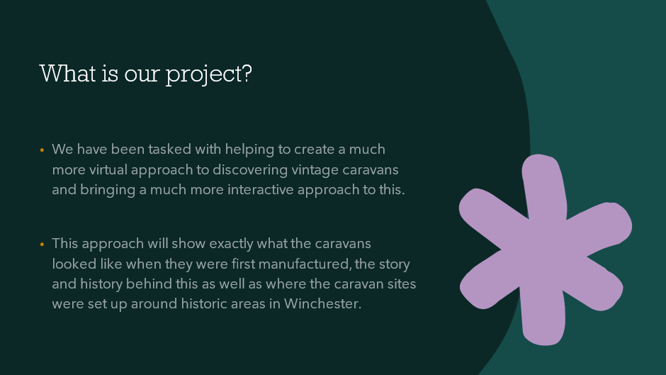
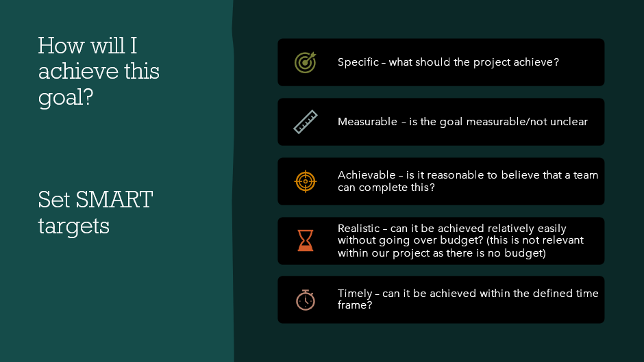
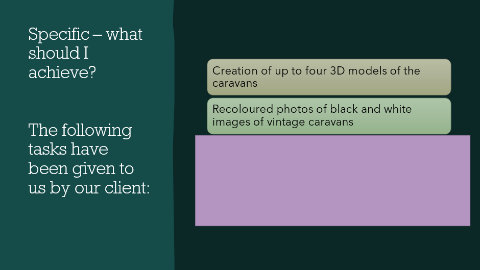
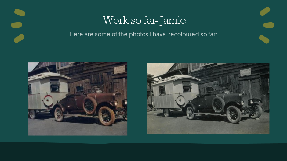
The client project I decided to take on for the semester was the CAMC Hutchings Caravan project. This project consisted of tasks such as recolouring old photos of caravans, creating a virtual look for vintage products and making a 3D model of a chosen vintage caravan. I decided to pick this as my project alongside three other CAD students as I wanted to expand my 3D modelling skills and thought this project was extremely interesting in general. An overview for this project as well as the research behind it can be seen in the presentation that I made mid-way through the semester:
It is also important to note that due to the nature of this project, I could not link SDG 17 into this. Below is a detailed explanation of the creation of my 3D caravan model:
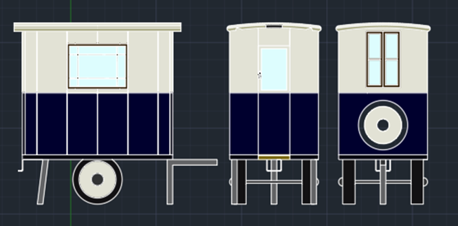
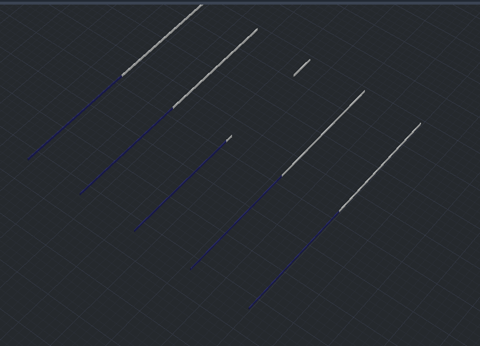
The first step I did was copy the two recoloured photos over into the AutoCAD software and trace over the lines of the exterior of the caravan. By measuring the angles and lengths and comparing the two photos to each other, it gave me an appropriate scale factor of approximately 1:1.25 from photo 1 to photo 2. With this factor it will help me determine the size of certain objects displayed in one photo and not another. I also rounded each measurement to two decimal points for the sake of ease.
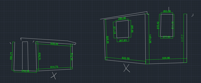
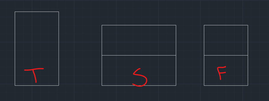
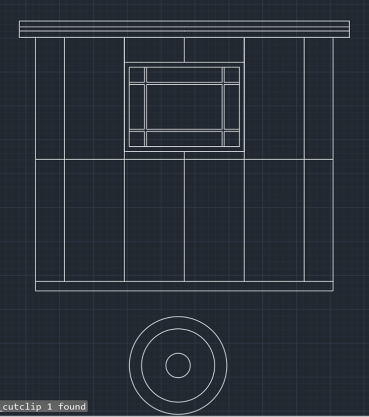
After gaining this scale factor. I mostly went off photo 1 for my measurements. I decided to draw the caravan in detail as a 2D drawing first as I felt it would make it easier to transform into 3D using this drawing. To start this off, I created a top (T), side (S) and front (F) view with the measurements of 11,000cm x 6500cm x 9000cm. I also drew the line down the middle of the side and front views as this matched the pattern in the photo.
Next, I added minor details which I would use as markers for the more intricate parts of the design later in the drawing. These minor details included the door (with window and handle), side window and the beginning of the roof such as the first basic shape and the overhang. All of this could be completed simply using the line tool.
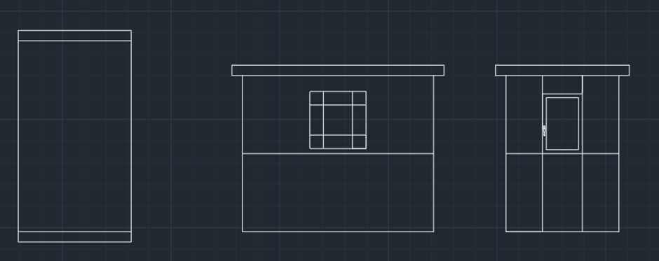
Then came some of the more detailed parts of the drawing such as additional roofing designs, adding the ridges seen on the side of the caravan and creating the “base” that the caravan sits on. For the front view of the roof, I used a mixture of the trim, arc, offset and extend tools to copy the shape over accurately from the photo.
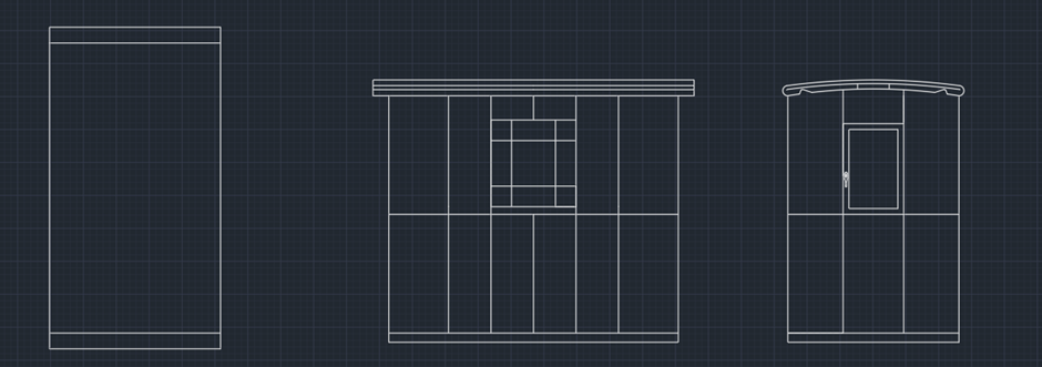
Once this has been done, I used the offset tool to re-enforce the window on the side. I also copied over the front view and removed the door whilst adding a tire and set of windows in replacement as this would now be the back view.
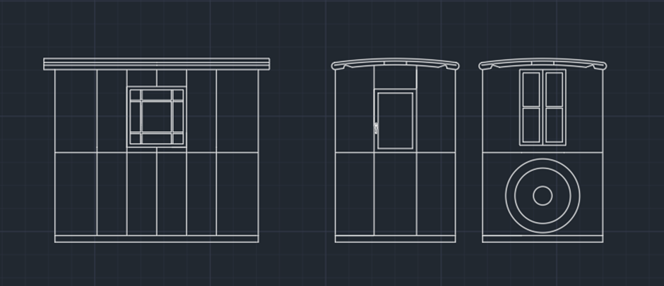
I thought that the tire may have been too big on the front view, to test this out I copied it over and set it underneath the side view as this would be the same size of wheel. I used the scale tool to make the tire slightly smaller as I felt it looked a bit more accurate, despite what my scale factor suggested.
The wheels were then inserted underneath the base of the drawing, they have a dedicated gap on the underside of the caravan, and this will be seen better in the 3D model.
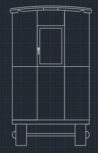
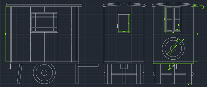
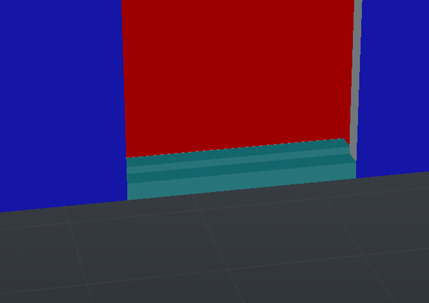
For the final details, I offset the individual ridges on the side of the caravan, added the small step seen below the front view and added some of the metal supports seen below the caravan.
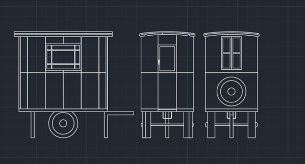
I also copy and pasted these drawings over twice. One was hatched to make each part more visible as both a 2D drawing and as a reference for each part and where they go. The other drawing was annotated in certain areas that I would need when developing to 3D.
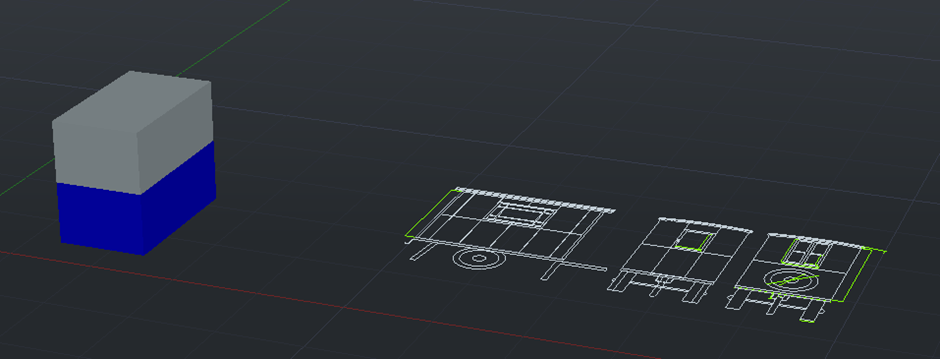
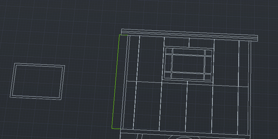
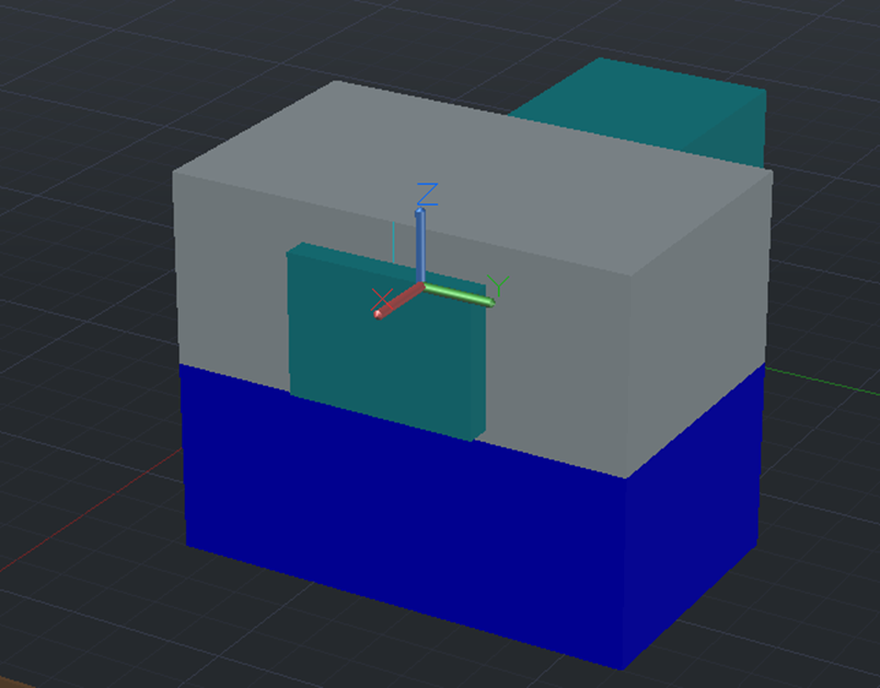
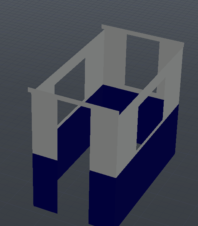
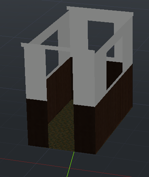
For the start of the 3D development, I created an AutoCAD 3DISO file and copied over the annotated drawings to paste on the floor of the plan. I then used the measurements on these to create the main “box” of the model. I created this in two parts as this would make it easier than creating the whole model and splitting it later. I also created multiple layers such as windows, walls, underside, wheels, roof and framing so that I could differentiate each part easily.
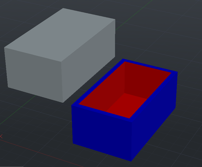
To hollow out the box, I created a box that was smaller by 100 in each dimension, thus giving the wall thickness of 100cm. It was then a matter of copying this subtraction box into the centre of both the blue and white cubes and subtracting separately to hollow them out.
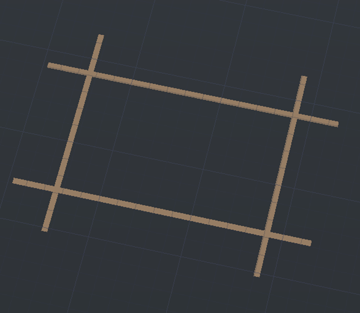
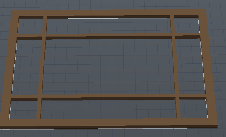
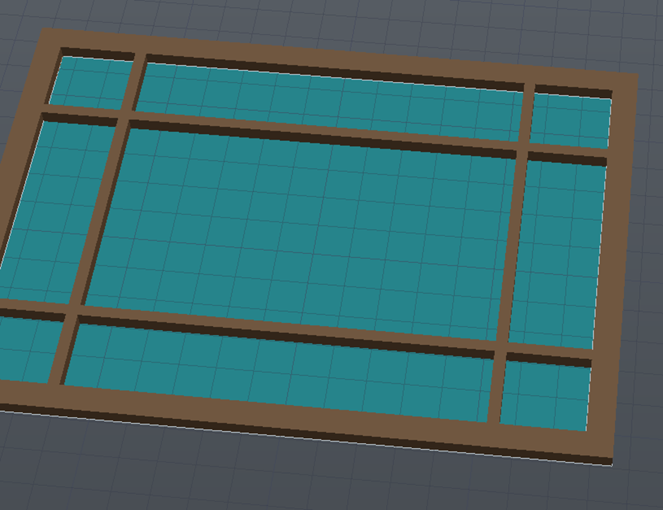
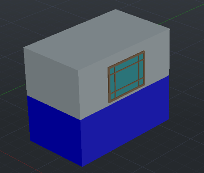
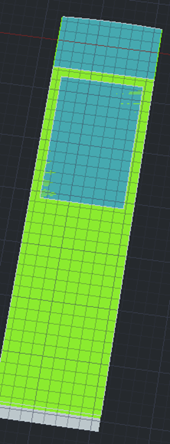
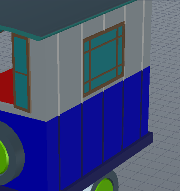
The first detail to create was the window, I did this by copying the lines of the annotated drawing and using the planar tool to create a base mesh. I then used the extrude tool on the wooden portions and raised them up before making the glass also using the planar tool and extruding by much less
After this, I created a box the same size as the window outline and placed it proportionately to the 2D drawing. It was then a matter of extruding the shape to be long enough to take out both walls and subtracting from the white box to be replaced by the created windows on both sides.
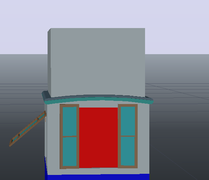
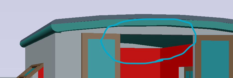
I repeated this for the back window and subtracted a small rectangle as this is where the roof will be inserted later on.
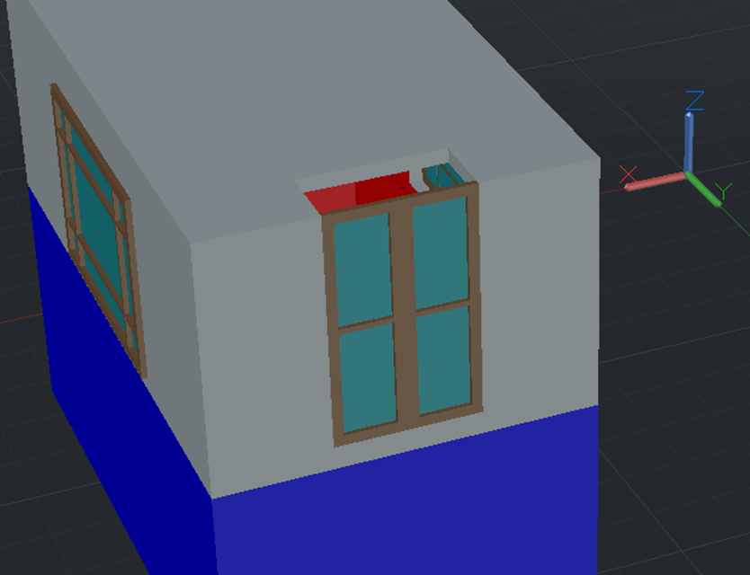
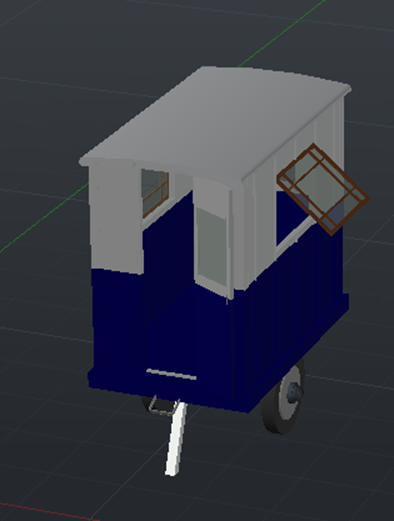
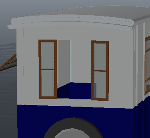
For a bit of added detail, I opened some of the windows using the 3D rotate tool.
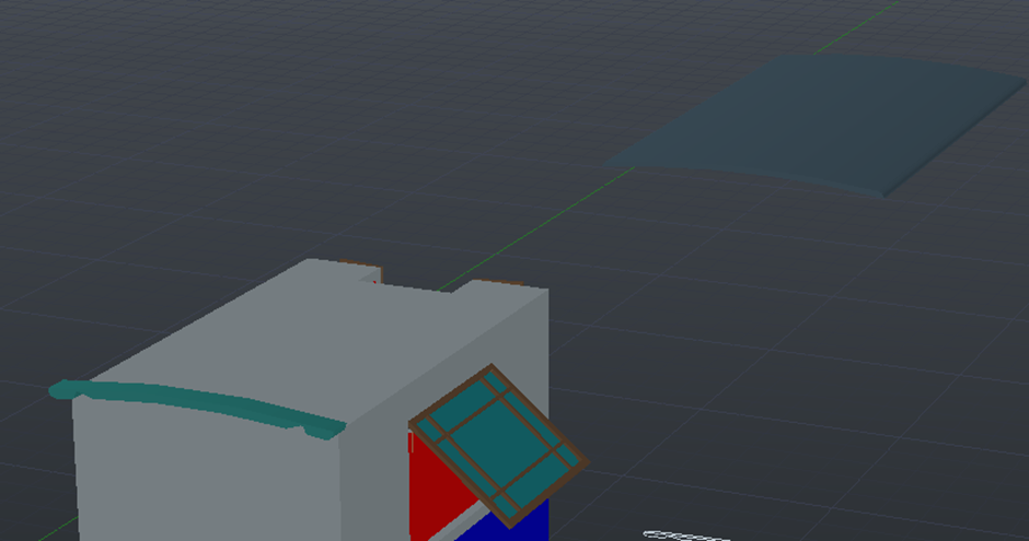
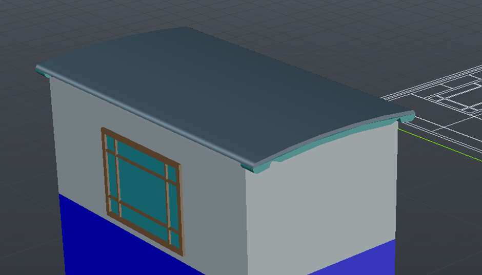
By using the same method as the windows before, I copied over the two roof segments whilst extruding and placing accordingly to the plan.

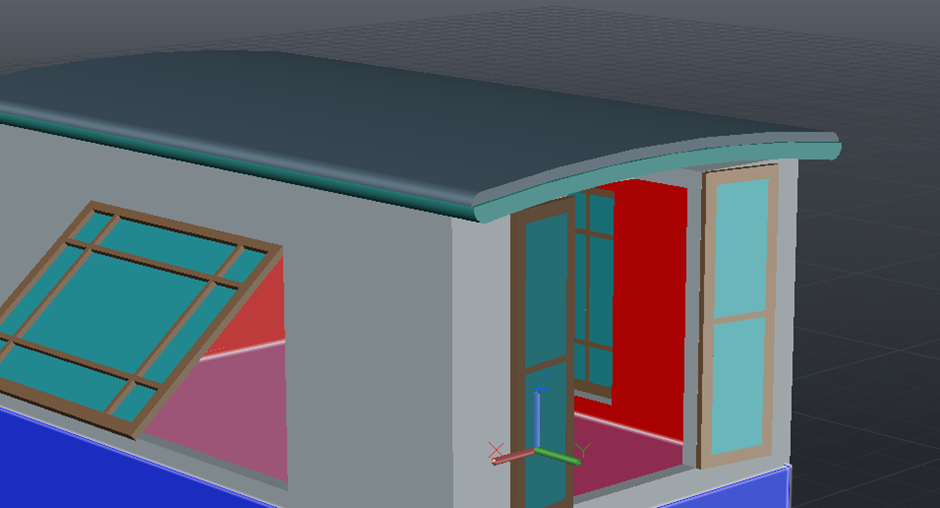
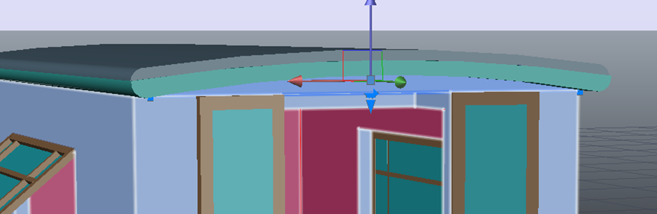
For the back window, I created a large rectangle and subtracted all of it apart from the part that connected the window frame to the roof. This filled in the gap created earlier.
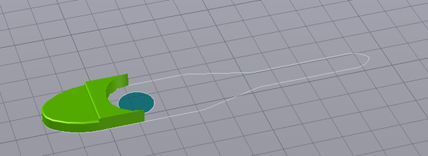
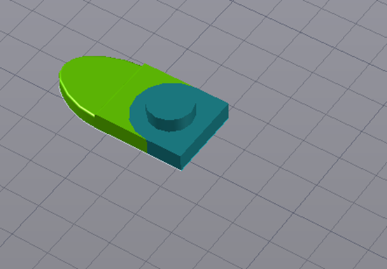
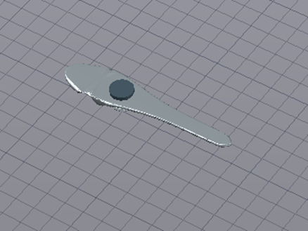
The handle for the door was a bit trickier to make, however, by combining the planar, extrude and mesh tools, I created a smooth looking object.

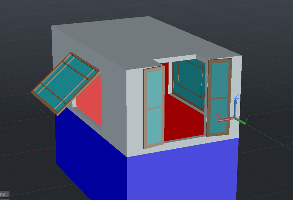
Next came the door, I used the same trick as before with the difference in this being that I extruded the top and bottom parts separately as these would need to be subtracted from the boxes. With all of this done, I could now subtract the rectangular shape and insert the door.
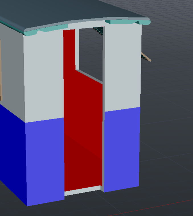
I also inserted some steps and attached the handle to the door before adding the final door to the model and rotating to make the interior more visible.
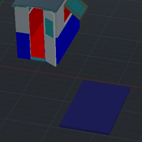
The base was the next part, the beginning of this was made by creating a box that was 50cm larger in length and width, ready to be placed underneath the model so far.
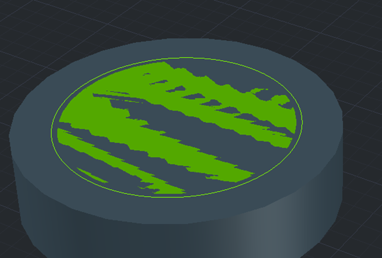
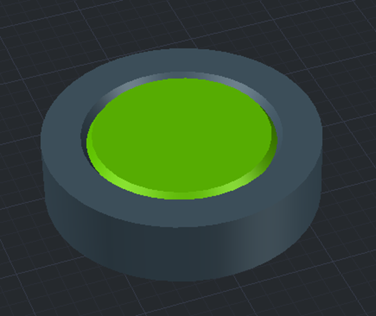
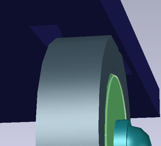
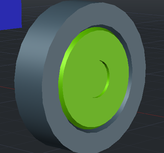
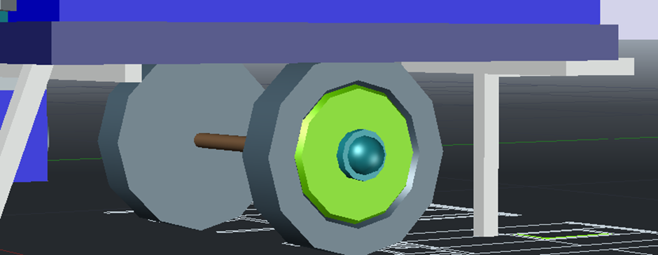
The wheel needed creating before continuing as this would be crucial to build the base around. I created this using a mixture of the taper angle extrusion tool and sphere tool.

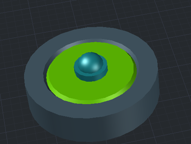
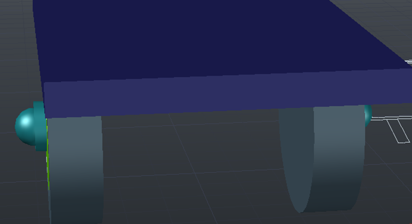
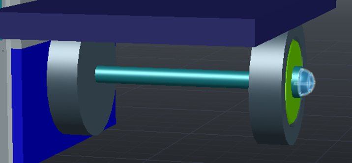
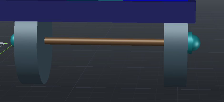
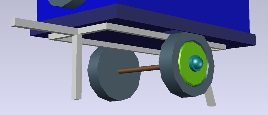
Even though the wheel looked rather cartoony and blocky at this stage, this was more for reference for a more detailed wheel to be added at a later point. I copied and mirrored the wheel to both sides of the created base before subtracting a small box from both sides of the base to make way for the wheels insertion and connected both wheels with an axel.
Another wheel without the axel also needed to be created for the back of the caravan.
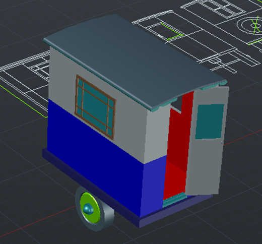
With this being done, I copied the rest of the model on top of the base and made the wheel axel slightly thinner as it did not look correct before.
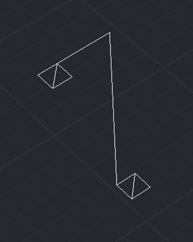
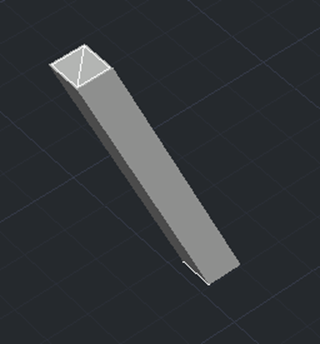
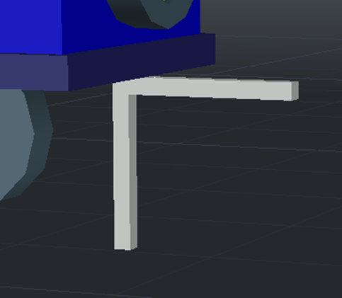
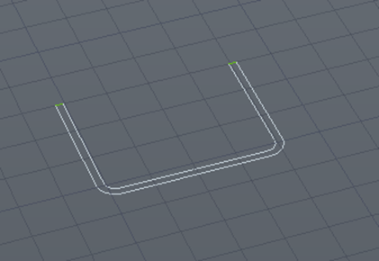
The underside framing was the next part to be added. This was done by using the line, square and extrude to path tools as by connecting the centres of both placed squares and extruding this path, it created the shape I required. This could now be added to the model.
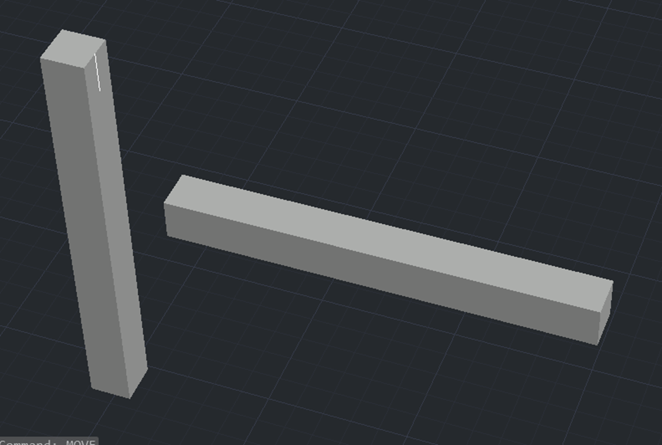
The next parts of the framing were extremely simple as they were just two basic rectangles. It looked out of place but this is exactly as they look in the drawing, so I decided to stick with the “blocky” framework.
To finish the framing, I created a basic frame underneath the base and connected with more rectangles accordingly.
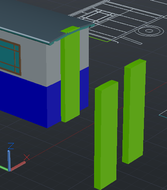
The ridges seen on the side view also needed to be added, I created these by tracing and extruding the lines on the drawing, setting their layer and placing on the model itself.
Another part that needed to be added were the corner points, these were added easily using the box tool.
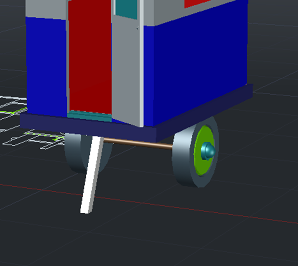
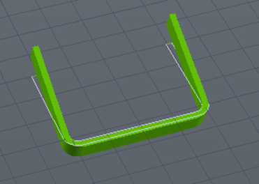
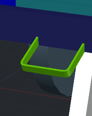
The final part of the exterior to be added was the foot handle, this was made easily with extrude and 3D rotating tools.
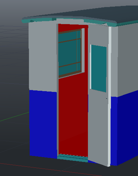
At this point, I had realised that the door was not split down the middle. To fix this, I copied two of the door parts and subtracted a box from each of the parts for each half. I then combined them, put the parts in the correct layers and placed the door back to its original space.
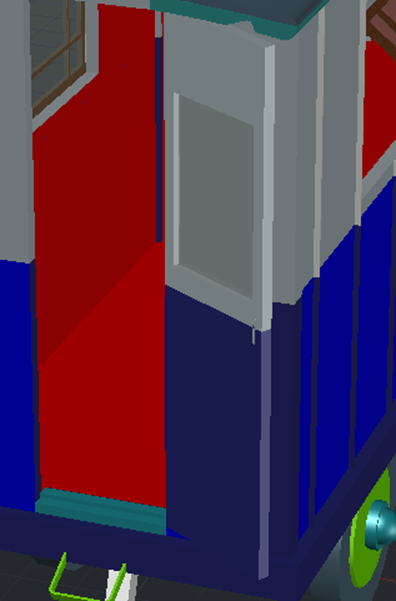
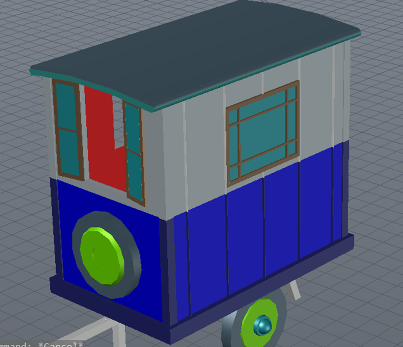
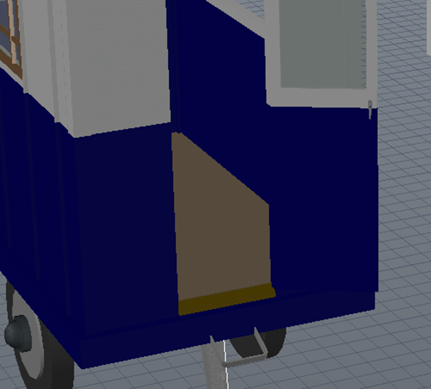
Like the hatch drawing made for the 2D model, I decided to decorate the 3D model to make it easier to understand each individual part and see if I am missing anything. To do this, I used the material assigner and placed accordingly.
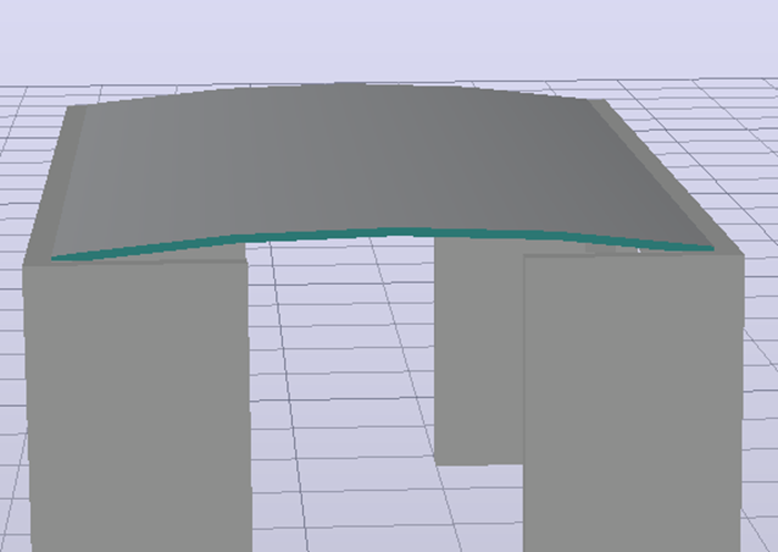
It was now time to design the interior, to begin this, I copied the underside of the face of the roof and the white subtracted box. I subtracted the box from this face and extruded the face upwards as this would be the ceiling of the model.
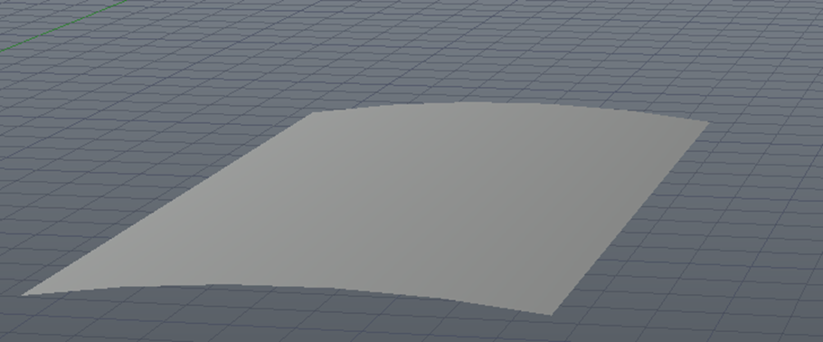
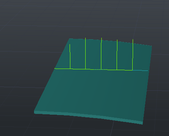
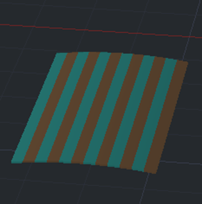
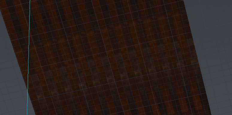
As these would be wooden panels, I used the line tool to split the roof in half, then measured out the remaining roof part. This could now be used to split the measuring line into 6 separate parts. By using the split tool, I could now separate this half roof part into 6 panels and by repeating the process and mirroring the half part, it now made a full roof split into 24 panels. These panels could now be assigned different wooden materials.
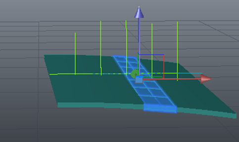
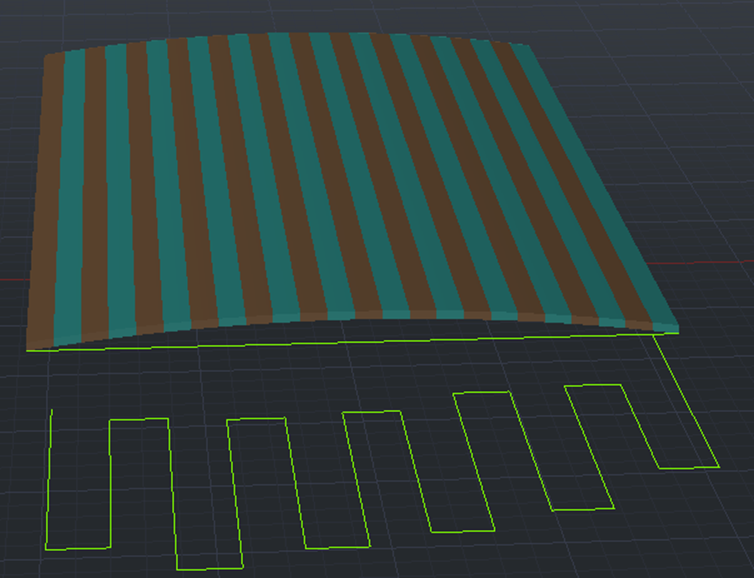
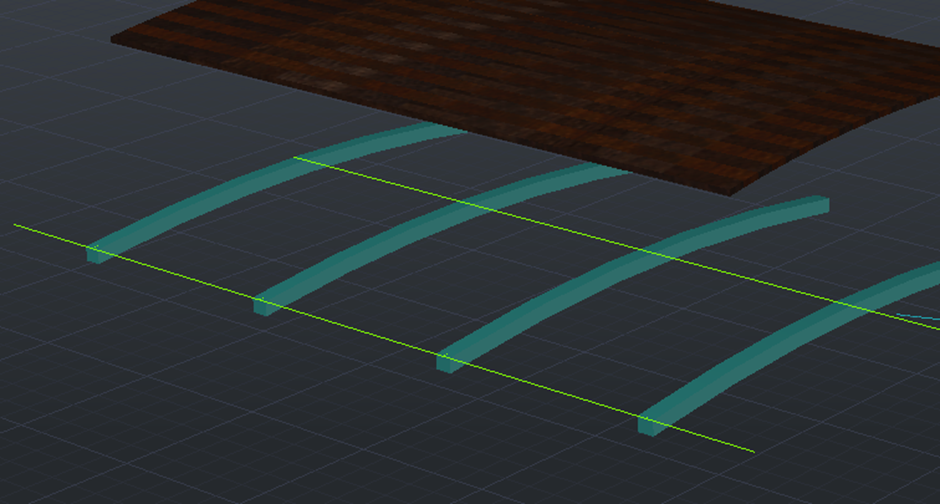
Next, I copied the original extruded roofing piece and made it much shorter but also a bit thicker. This new piece could now be copied 4 times and placed along the panels made in the last step.
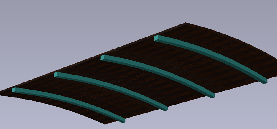
A small flooring piece was placed into the model at this point.
The interior walls were the next part. To make these, I copied the interior faces of the caravan and moved each of them in by 1mm before trimming so they would fit in perfectly. I also realised at this point that the window at the back of the caravan was placed too high, so I moved this down and adjusted the wall around it.
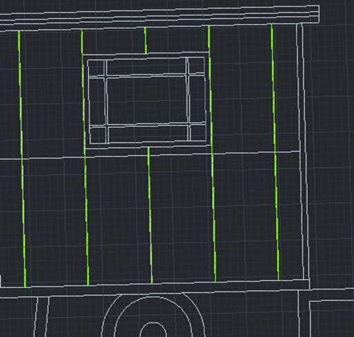
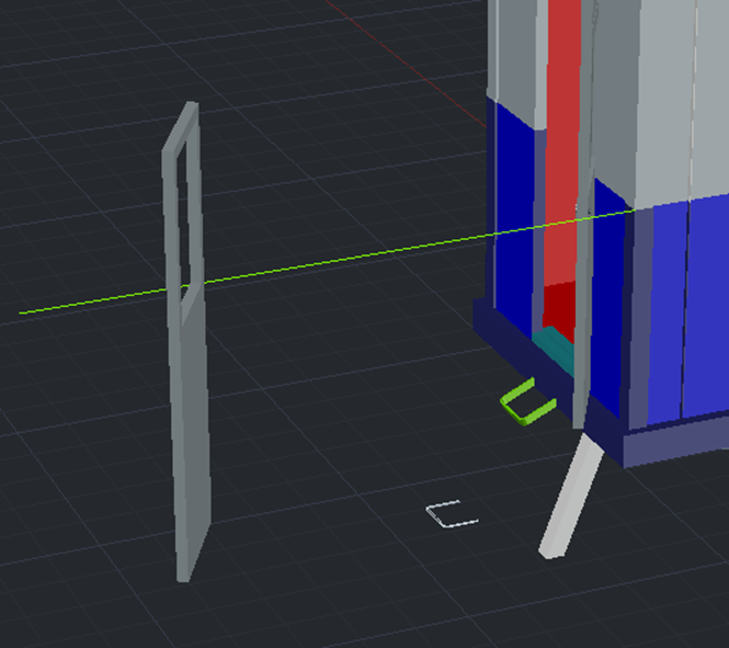
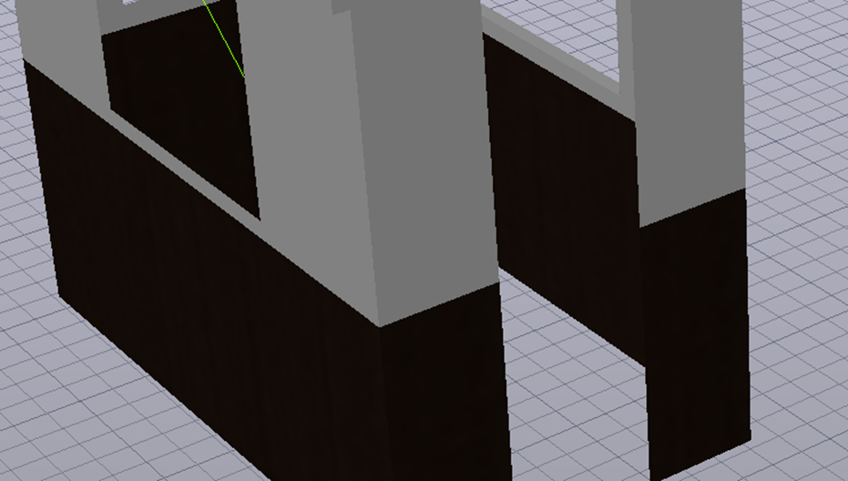
I could now change the materials of the inner walls and the flooring. Once this was done, I used a green line as reference to paste the walls back into the model space.
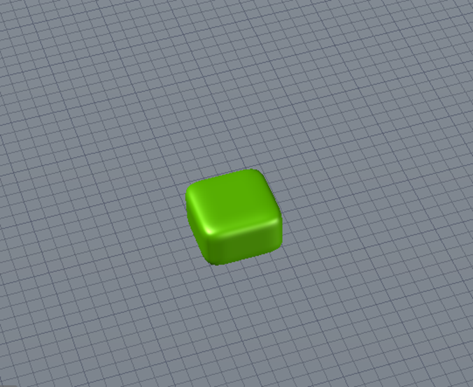
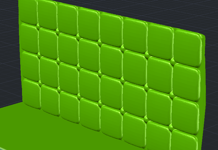
Unfortunately, I knew AutoCAD wasn’t the best software for the software for creating the sofas. However, I made a good attempt in creating this. The first thing I did was create a small cube and use the mesh tool to smooth it out.
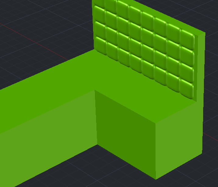
By copying this square multiple times atop and beside one another, I could now copy this on to some basic cubes measured using the interior of the caravan. I also made a back plate which could now be merged with all the individual cubes and smoothed out.
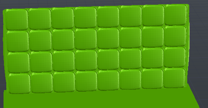
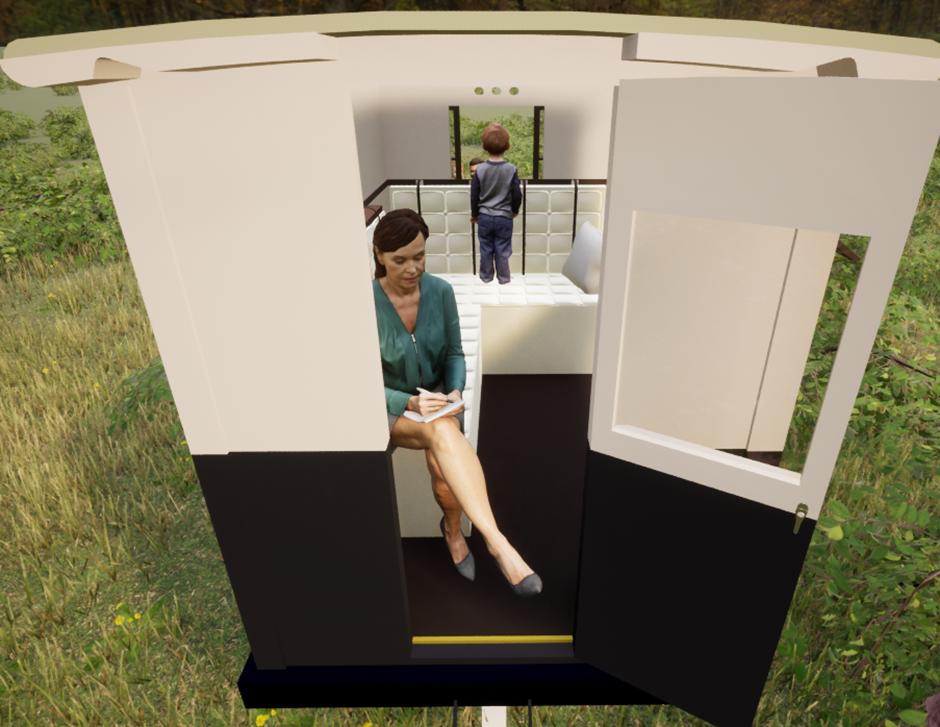
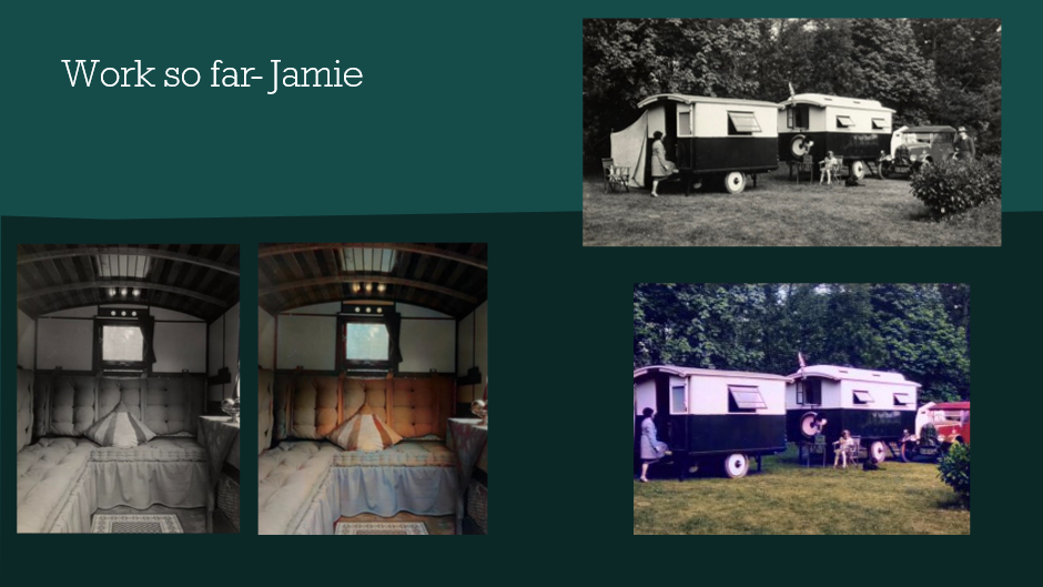
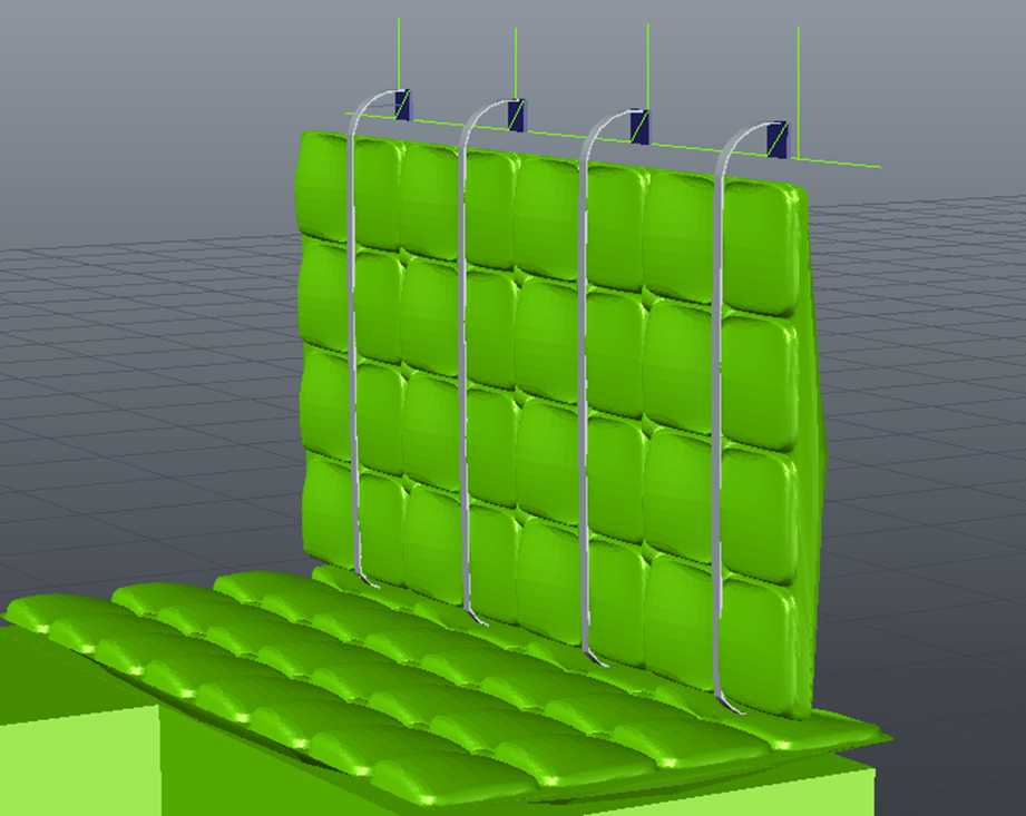
As this was created with the mesh tool, I could now pull out the spaces in between the cubes to create the cushion pattern. I also pushed back the middle of certain squares as this is where the belts, as seen in the interior photo, will be placed.
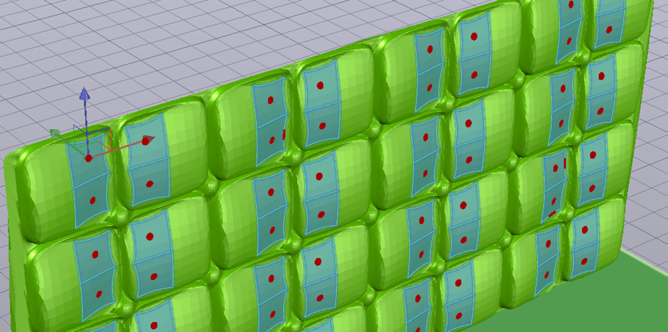
For the belts, I measured out the backplate and placed small squares where each belt would be placed. Now by using a mixture of the polyline and extrude to path tool, I could draw a small belt on each square as well as a line crossing over the cushion and extrude so that the belt would come out covering the cushion completely.
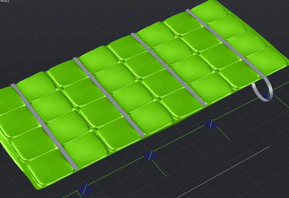
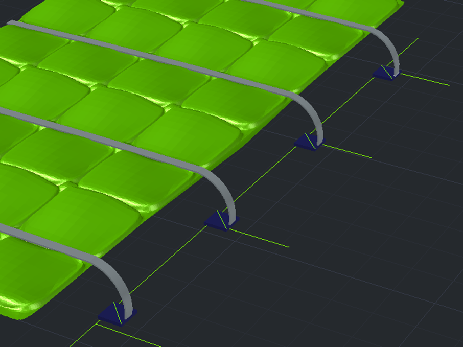
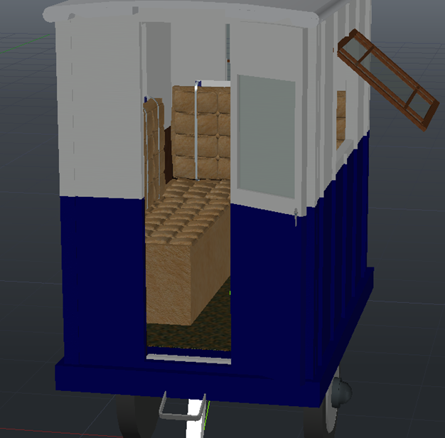
I could now rotate this and rotate to be vertical. The initial cushion shape was copied over too as the base of the cushion and these would now combine and be copied over to complete the model. This was now ready to be given a material and added into the interior. This gave me a final model that I was happy to edit and transfer over to TwinMotion.
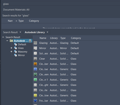
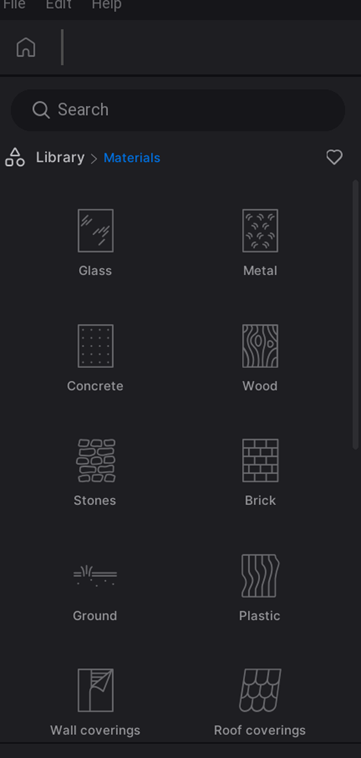
As I had not used TwinMotion before, it took a bit of getting used to. I utilized the day and night template as I felt this would give a more realistic look to the model. I set the time of day of the scenario to 13:00 as I wanted it to be viewed in sunlight. I then utilized the materials library and assigned where needed, similar to the method used in AutoCAD.
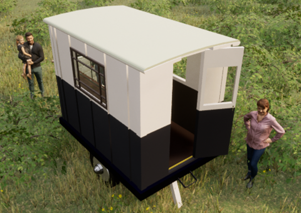
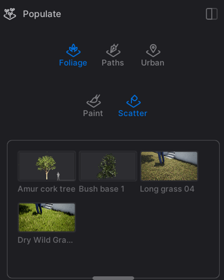
With this being done, I could now populate the environment. I used the scatter tool to add nature items such as bushes, long grass, trees and branches. I also utilized the library again to add still models of humans, this was added to give an idea of scaling as well as making the final product look more dynamic.
With all these stages finally being completed, I am now more than happy to showcase the final render of the Beaulieu Caravan Project: