Introduction
For the first project of my third year, we were tasked with either completing placement within an industry over a certain time frame or completing a pre-existing or new client project. I decided that with a hope of entering the theme park industry, I wanted to create a 3D model of a pre-existing roller coaster. This would give me a good experience in researching what it takes to design a coaster and an introduction to 3d modelling coaster assets. The main reason behind focusing on this project is my passion for the theme park industry. This roller coaster model is something I have wanted to complete for a long time and is an exciting opportunity for my design career.
The following report serves as a reflective analysis of my creation of the roller coaster model. Throughout this project, I aimed to not only showcase my technical skills and creativity but also to address the importance of sustainability and ethical consumer behaviour within the industry. To complete this task, I set out a list of objectives that I wanted to achieve along the way. These include:
. Provide a background and overview of the project whilst focusing on considerations and key focuses.
. Analyse the sustainability factors of the project and investigate any ethical issues that may be present.
. Investigate Sustainable Development Goal 12 and how it may relate to potential consumers’ needs and wants.
. Create the scaled roller coaster model and demonstrate techniques used along the way.
. Critically evaluate the final model and find any improvements that may be made as well as future possibilities.
Background and Project Overview
With the project set I had to think about the possibility of 3D printing after completion. This was a heavy part of what I wanted to do with the finished coaster model and would be a large factor in the design as I’d have to make separate parts and connectors that would need to be printed separately to fit the model together. In the end, I decided not to 3D print due to a mixture of time constraints and complexity. I did still make the model in a way that has potential to be 3D printed and this could lead to a future project in which I complete this task.
The first step of creating the roller coaster model was deciding what coaster it is I actually wanted to build. I had the choice of creating my own custom model or basing one off a pre-existing coaster from around the world. I decided against making my own custom model as I felt this would bring about many problems. These would include being on a strict time limit and not being able to complete a decently made model in time, struggling to find an appropriate scope / scale factor, and not having a finished product to compare to whilst producing the model.
Once I had decided that I was going to use a pre-existing roller coaster, I had to make a decision on which coaster I was going to base it off. In the end, I narrowed it down to three roller coasters and performed a SWOT analysis on each of them in regard to how they would be modelled:
Colossus – Thorpe Park
Strengths: As the worlds first roller coaster with 10 inversions, Colossus has built up a reputation of being recognizable around the world and could be a great opportunity for future job prospects with the owners of the UK’s biggest theme park company and owner of Thorpe Park, Merlin Entertainment.
Weaknesses: Colossus having 10 inversions would make it extremely difficult to model on any software. If I had a bit more time, this may be a possibility, but I feel that this coaster may be too much to handle at this stage of my design career.
Opportunities: Due to its location in Surrey, it is not too far from Winchester. Because of this, there would be a possibility that I could go and visit the coaster in person. By doing this, I could see new angles not otherwise found online and build a better visualization of the roller coaster for myself.
Threats: Due to the coasters shape, if I were to eventually go and 3D print the coaster model, it would be an extremely difficult process and could lead to the model collapsing or not supporting the weight of the coaster car. It is also possible that the model would not be completed within the given time frame.
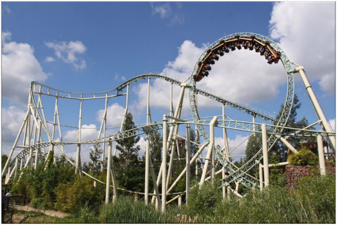
Scorpion – Busch Gardens

Strengths: Scorpion is the perfect blend of simple yet intense with its easy design providing a great base for a roller coaster and the loop adding a layer of complexity that will help the model look much better when completed.
Weaknesses: As this roller coaster is based in Tampa, Florida there is no chance I could look at this in person before the deadline of the project. It is also a very niche roller coaster with not too much recognizability worldwide.
Opportunities: The owners of Busch Gardens are the SeaWorld Parks & Entertainment Group. This company runs some of the largest theme parks around the world and could be a great company to showcase my model to.
Threats: Due to its low recognition, documents and stats for the coaster may be hard to find online making it harder to build the model to the correct scale. The loop is also a threat to this model and may be difficult to create within the used software.
Santa Monica West Coaster – Pacific Park

Strengths: This roller coaster is extremely recognizable as its location is one of the biggest tourist hotspots in California. It also makes a notable appearance in the second-best selling video game of all time, Grand Theft Auto 5. Because of this high recognition, this coaster model could be showcased in a multitude of locations.
Weaknesses: Similar to Scorpion, I would be unable to access this coaster in person and would have to rely on images and videos posted online to model this. It is also an extremely simple roller coaster, and I would like to give myself more of a challenge if possible.
Opportunities: With this ride operating on a pier, the ground floor would always be flat making it easier to model and scale than other coasters.
Threats: As the roller coaster is quite small, this may be an issue when creating the model due to smaller parts and more compactness. This may also make it difficult if I were to go and 3D print the model after completing.
After evaluating each of these coasters, I decided to go for Scorpion in the end. Due to its simple yet intense design and opportunities in the industry, this made it the perfect roller coaster to try my hand at for a first attempt.
Ethical and Sustainable Evaluation
As this is an online model, there is a need for a level of energy consumption to power the software and hardware used for the creation process. Things such as low power and sleep modes on the laptop used will help to reduce this energy consumption and rendering through TwinMotion as opposed to other rendering software drastically reduces energy consumption.
Another factor to be considered is the 3D printing process. Even if it is not being printed throughout the duration of this project, the model is still being made with the idea of printing in the future. Things such as materials used, fumes created by the 3D printer and energy usage of the printer may be heavy factors to consider ahead of the printing process. To counter each of these, I have decided that if or when I am to print this model, I will complete this in the 3D lab at Winchester University. This room has ventilation systems to counteract the fumes created by the printer. It also allows me to pick out materials ahead of time. By doing this, I have outlined PLA plastic as the best material to use. This is due to it being made from renewable sources such as corn-starch and sugarcane. It is also biodegradable making it the perfect material for this project.
Needs & Wants in Relation to Sustainable Development Goal 12
With Sustainable Development Goal 12 putting a strong focus on calling for businesses to adapt to more sustainable practices, the needs and wants for my potential consumers may come into play when designing this model.
To properly complete this analysis, it is important to first focus on who my potential consumers may be. In this case, there is potential for the SeaWorld Parks & Entertainment group to view my model and present this either in their parks or on their website. There is also a possibility of coaster enthusiasts potentially wanting to purchase the model for themselves.
The first consideration is prioritising the essential elements required to make the 3D coaster model and how I want it to primarily focus on the needs of being functional and appealing. By avoiding unnecessary features and excessive materials that may contribute to wase or resource depletion, this approach will ensure responsible consumption whilst still appealing to the wants of the consumers.
As mentioned in the sustainability analysis, if the model were to be printed, sustainable printing methods such as using PLA plastic and low energy printers would be utilized. I would also make sure to use such features as low power mode on my laptop and ensure that the model is completely ready before attempting to print to make sure that no reprints would be needed, therefore using much less energy.
The final idea could be implementing energy efficiency into the model. Ideas such as making the lift hill solar powered could be a great message for raising awareness about responsible consumption and production to the targeted consumers.
Model Creation
To start the creation of this model, I first had to find the statistics of the roller coaster itself. I took these from the Busch Gardens website as I knew that this would be a credible source. I gathered all the stats I needed and put them in a table:
| Height: | 60.7FT (18.5M) |
| Length: | 1817.6FT (554.0M) |
| Speed: | 41MPH |
| Inversions: | 1 |
With this done, I needed to decide how I was going to go about creating the model. I decided to stick with 3D AutoCAD with some work also being done on 3DS Max and TwinMotion. I chose AutoCAD as I had been practicing Fusion360 and thought this may be the best software. However, due to being fairly new and unsure on this program as well as the relatively slim deadline, I decided to stick with the software I was most comfortable with.
Another Benefit of using AutoCAD is its extraction method. Due to this and 3DS Max both being owned by AutoDesk, file formats are easily transferrable and editable within both softwares.
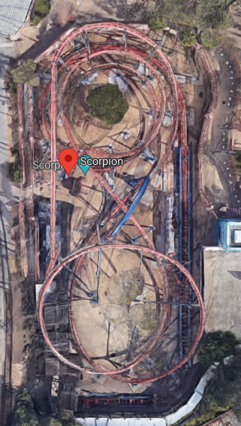
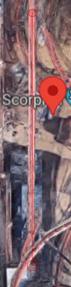
The way I wanted to begin this project is by scanning as many photos as possible of the coaster itself and looking for the best way to see all angles without actually being at the location of the coaster. To do this, I used Google Earth and made the most of its 3D landscape feature. Once on google earth, I took a top-down photo of the entire coaster as a reference I could post on the workspace in AutoCAD:
I then used the landscape feature to get side-on photos for more references:
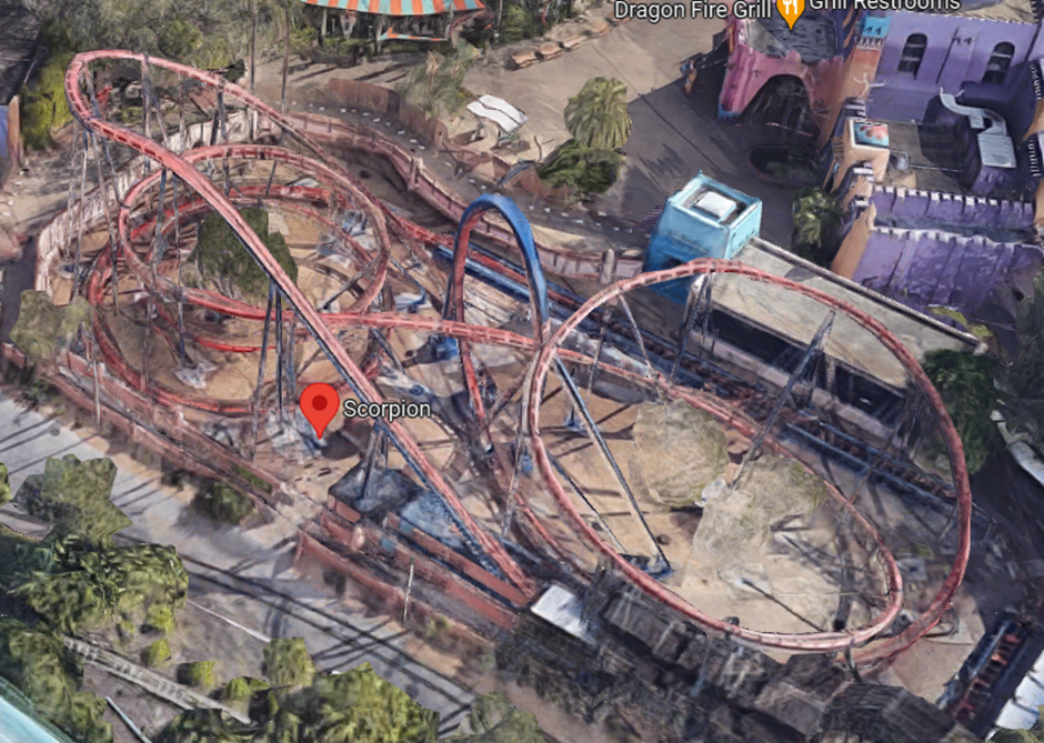
Although the roller coaster looks disfigured on Google Earth, the heights and lengths could be easily converted to find an appropriate scale factor and be accurate when making the model.
To calculate the points needed on AutoCAD, I marked the appropriate points as 60.7ft and 0ft with these being the peak heights and the base of the first lift hill of the coaster.
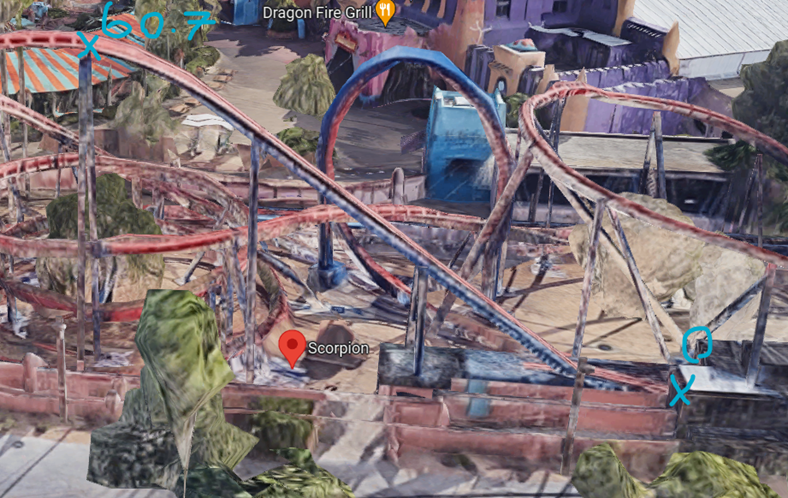
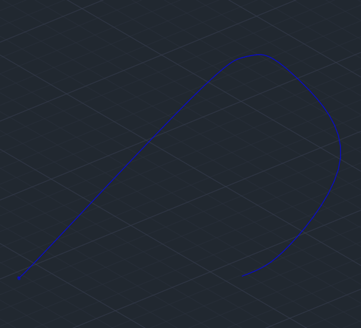
I then needed to calculate the length of the lift hill outlined below:
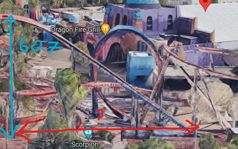
To do this, I pasted the photo into AutoCAD and measured the 60.7 height line as 1161 and the “?” red line as 1976. To find the scale factor, I divided 60.7 (actual coaster height) by 1161 (measured AutoCAD height) to get a SF of 0.0523. This left the length of the lift hill as 102.7.
Using this measurement, I could now paste this length on top of the top-down photo taken of the coaster model to scale it down and use it as an accurate point of reference.
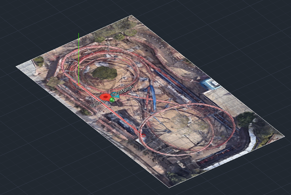
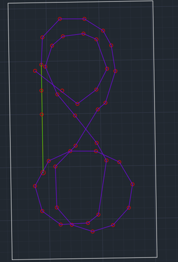
I then created layers and set to work. I created the light green layer as “measurement points” before drawing two lines using the previously calculated measurements representing the length and peak height of the lift hill.

Next, I zoomed in around the photo and placed a red circle where each support beam connected to the bottom of the coaster track.
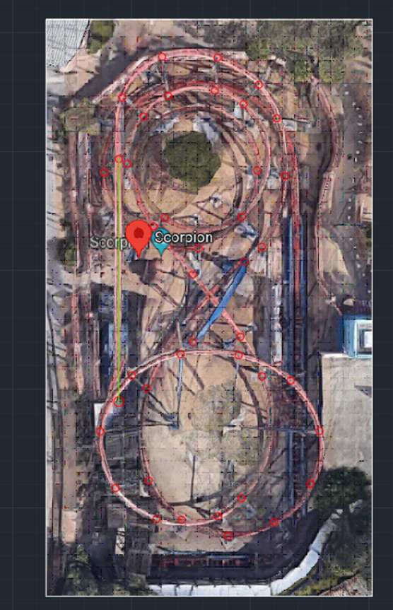
By doing this, it created a perfect template to insert the heights of each support beam, henceforth giving points of reference that the track would need to hit to be accurate. I could now also connect each of these red circles to give a basic look at how the track would look.
Once again utilizing Google Earth, I could now calculate the heights of each support beam due to Earth’s Ruler tool being able to calculate the height of each beam to the ground:

With the peak height of the lift hill (and the whole coaster) showing as 112.92 Meters. This was obviously wrong. However, this did not make the method useless as all measurements could be converted using a unanimous scale factor. With this in mind, I measured all the heights of the structures on google maps and noted them down alongside their respective circles:
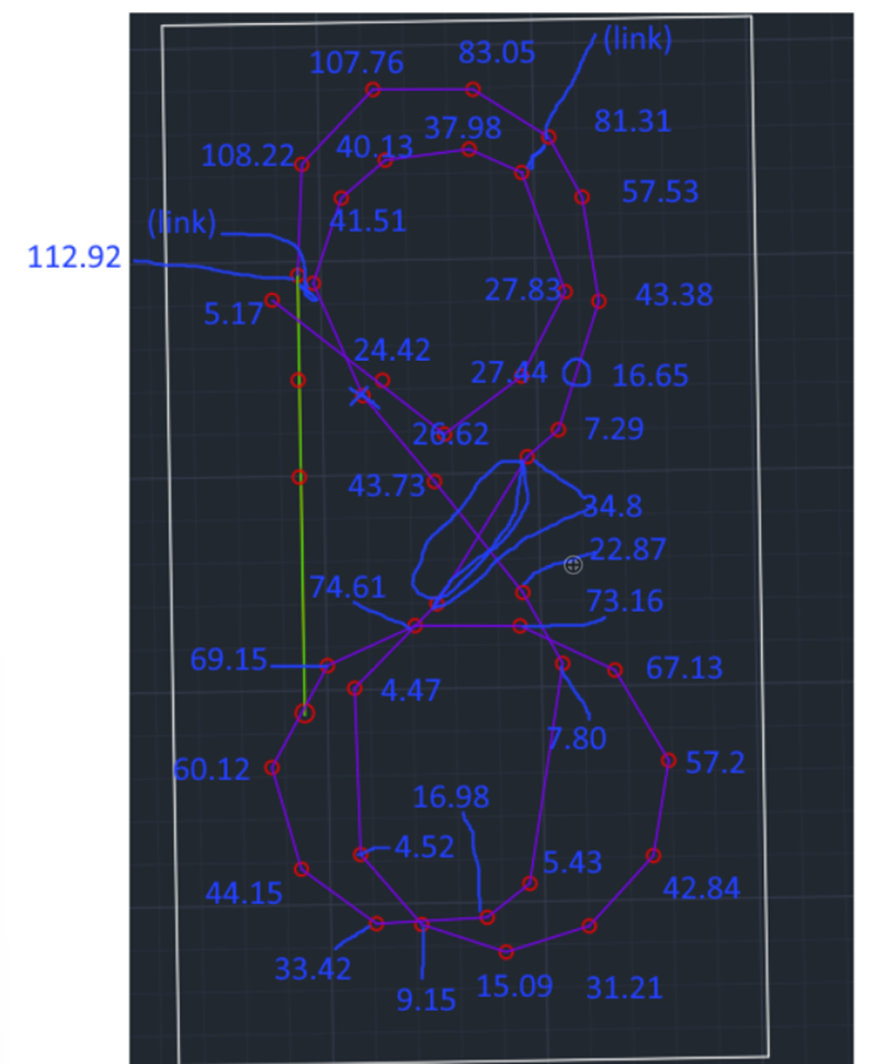
With 112.92M representing 60.52ft, the scale factor could be calculated as 0.536. I could now multiply this scale factor by each measurement and create lines representing the heights of structures on the workspace:
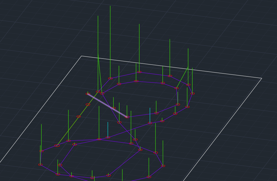
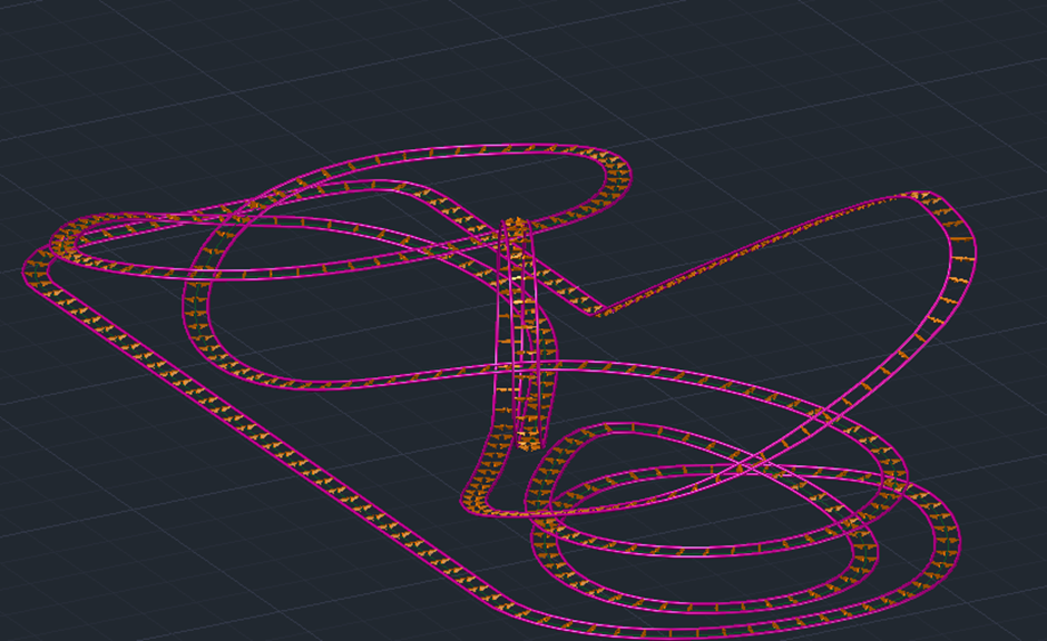
I then connected each of these structures with a light blue layer to represent the track. By utilizing the top-down photo of the coaster, I could also place blue lines on the ground of the model, creating reference points that would come in useful later on.
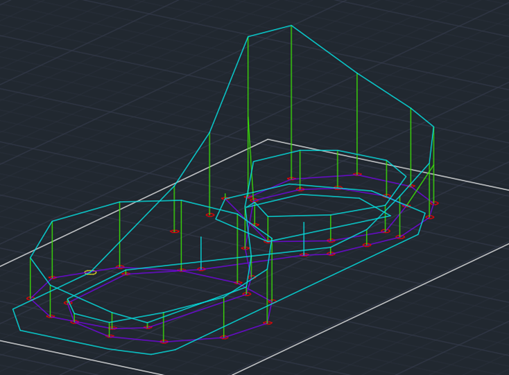
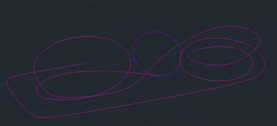
I decided to use a pink layer and make a polyline of the “track”. This would just give an idea of what the track would look like using the current reference points.

After seeing that the polyline was out of shape in multiple places and didn’t line up with how the coaster itself looked, I decided to place extra reference points (shown in red) in between each of the pre-established ones created.

I also recreated the loop using 3 circles and zigzagging to make a smoother looking line.

With this done, the prototype of the model was complete. It was evident that there was still a long way to go as not all the reference points were connected in the line and some curves were still looking out of place. At the time, this was what I had to work off and was hoping to improve it as I started to turn it three dimensional.

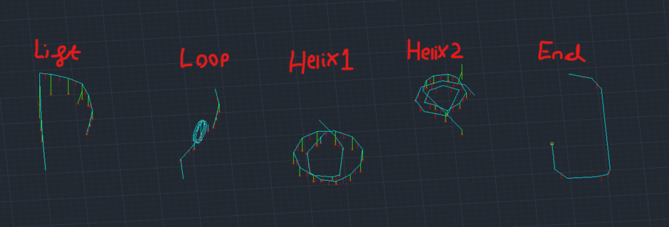
To give a better focus on the model, I decided to split it into 5 pieces with these being the lift hill, loop, helixes 1 & 2 and the ending. I separated and saved each of these parts into their own separate documents.

To make the lift hill segment, I made a circle to represent the middle piece of railing and extruded it along the created path line.
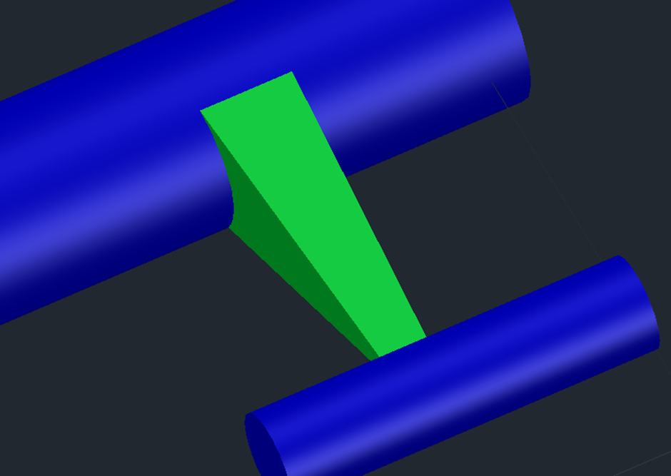
I then measured out the angle between the start of the lift hill and the ground and created a connector piece that would be used later to piece together the model:


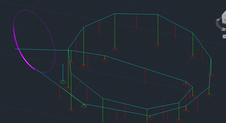
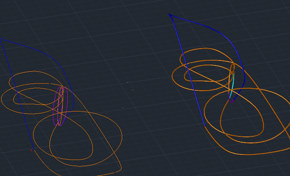
With the lift hill complete, I could now focus on the loop. To do this, I took the loop and lift hill pieces and placed them on the same workspace. This would allow me to connect the two parts easily.

The loop was to be constructed of three circles. One would represent the start of the loop; the second would be the inverted section connecting the circles and the third would be the exiting of the loop:
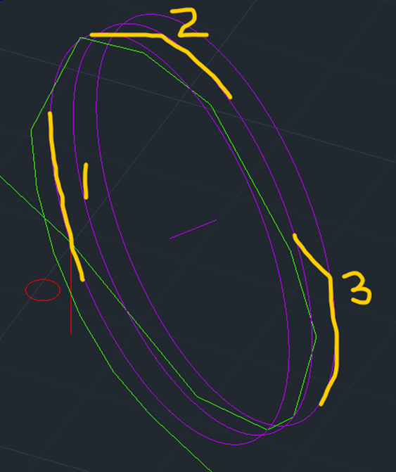
The next process required me to create a separate purple layer containing the three circles and a line and midpoint connecting circles one and three:

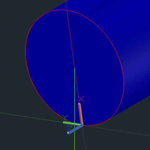
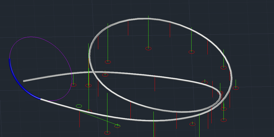
I could now invert the UCS and rotate the second circle to align with the endpoints of the created line, connecting all three circles.
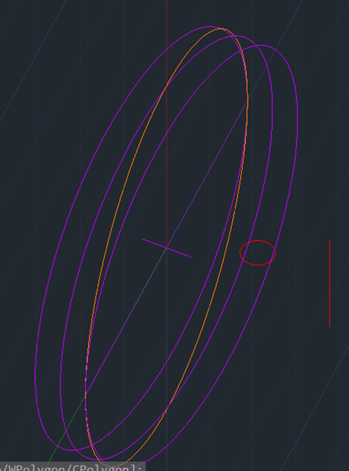
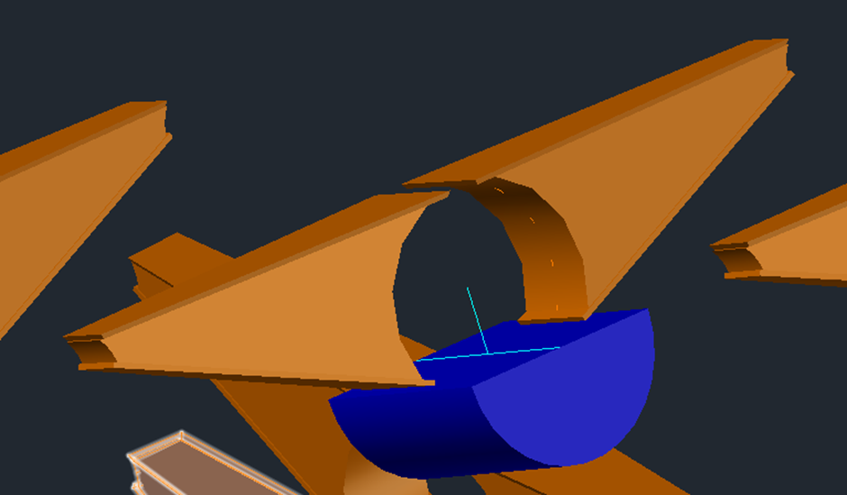
Now I could start to extrude the rail along the circles. By only extruding up to the midpoint line, it gave me two extruded semi-circles that would contain the foundation of the loop.

I repeated this process and flipped it for the middle loop:

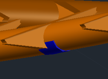
With this being done, I created a large block either side of the circles and subtracted it from circles one and three to erase the unnecessary track pieces:

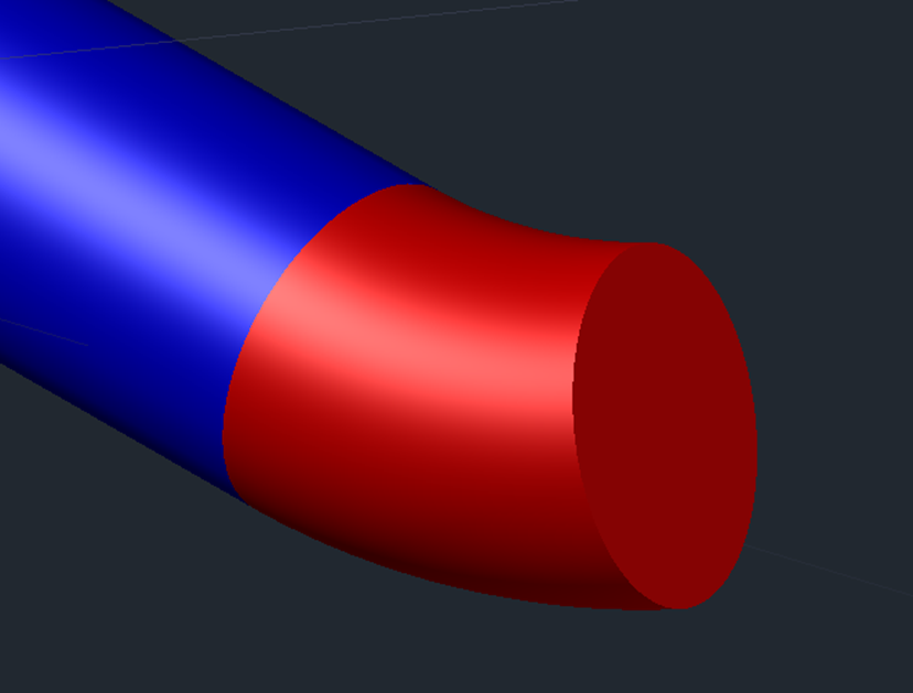
With the loop being complete, I made a polyline connecting the loop to the initial lift hill piece and extruded a circle to connect the two pieces.
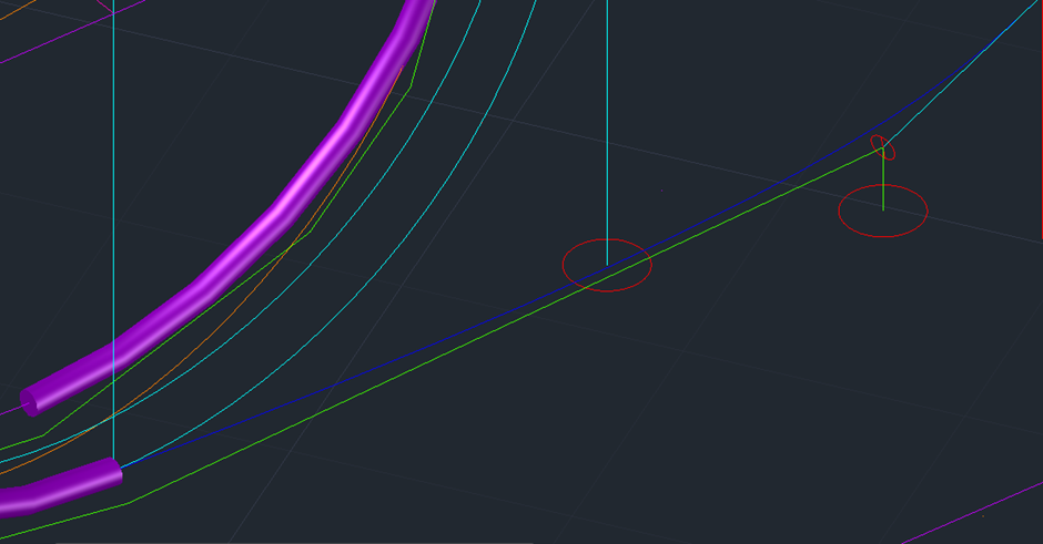
With the loop complete, I started on the first helix. I used the same method as before and simply created a polyline connecting the points and extruded a circle along it:

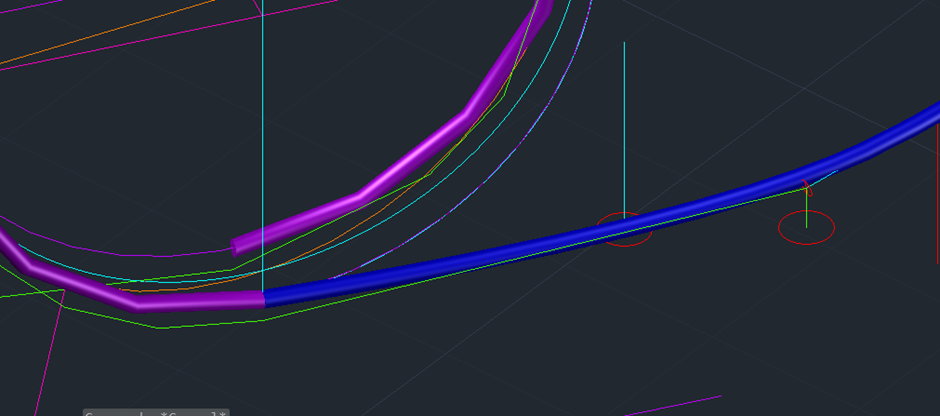
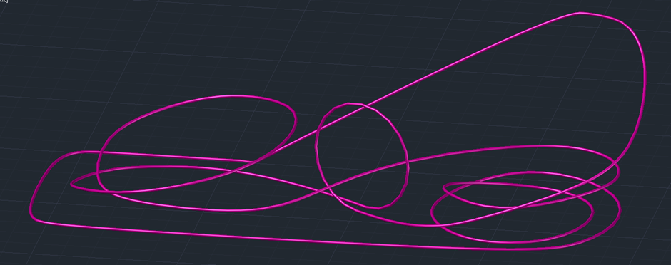
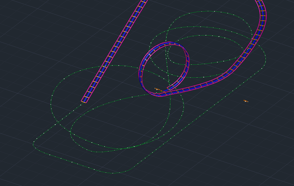
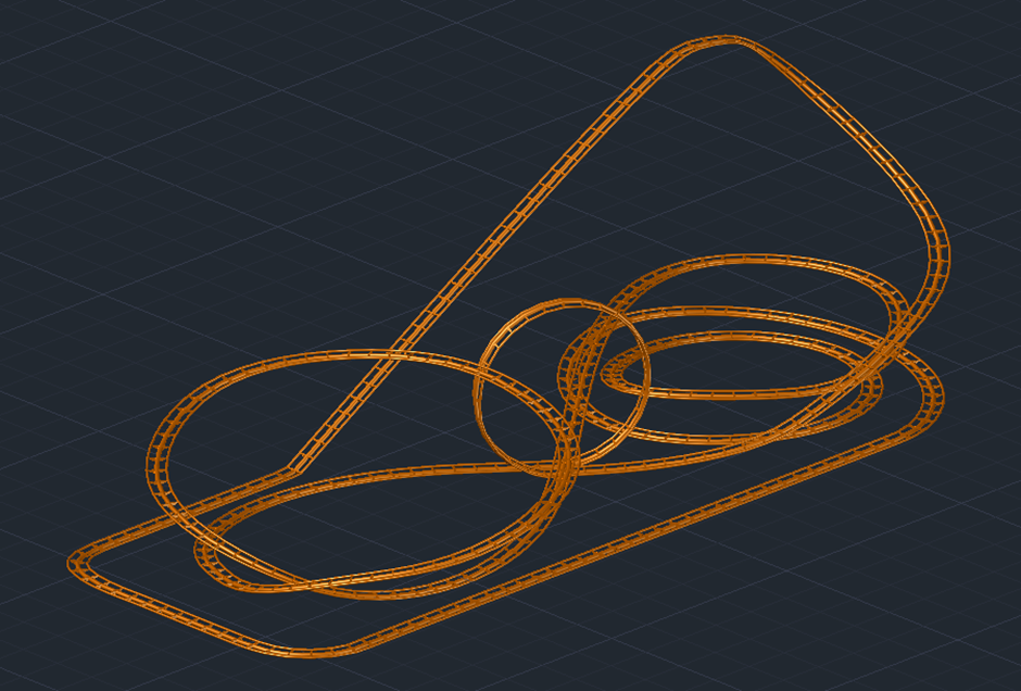
It was at this point that I become unhappy with my work as other than the loop, the model was not lining up with all the pre-established measurement points, making it not up to scale and inaccurate. I did some research online and found that by using the spline tool instead of polyline, I could connect all the structure points whilst maintaining the needed curve of the polyline.
By redrawing the lines using the spline tool, it lead to a much cleaner looking prototype model:
It also allowed an easier extrusion but due to a precise way of inserting the rest of the track later on, I decided to split the model into three parts instead of five and recreate the needed parts to be completely accurate.
With this initial rail now being complete, I could focus on the required track piece that would be placed along the spline at certain intervals.
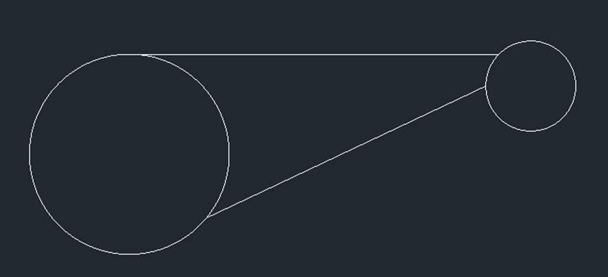
To start this track piece, I created two circles with one having a radius of 0.5 and one having 0.225. The 0.5 radius circle will represent the middle of the rail which has already been extruded across the spline.
I drew lines out the top corner and side of the smaller circle and connected them to the larger circle before trimming the unneeded pieces. By using reference images of the track, it allowed me to connect the lines exactly where they would on the coaster itself.

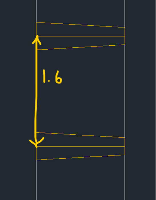
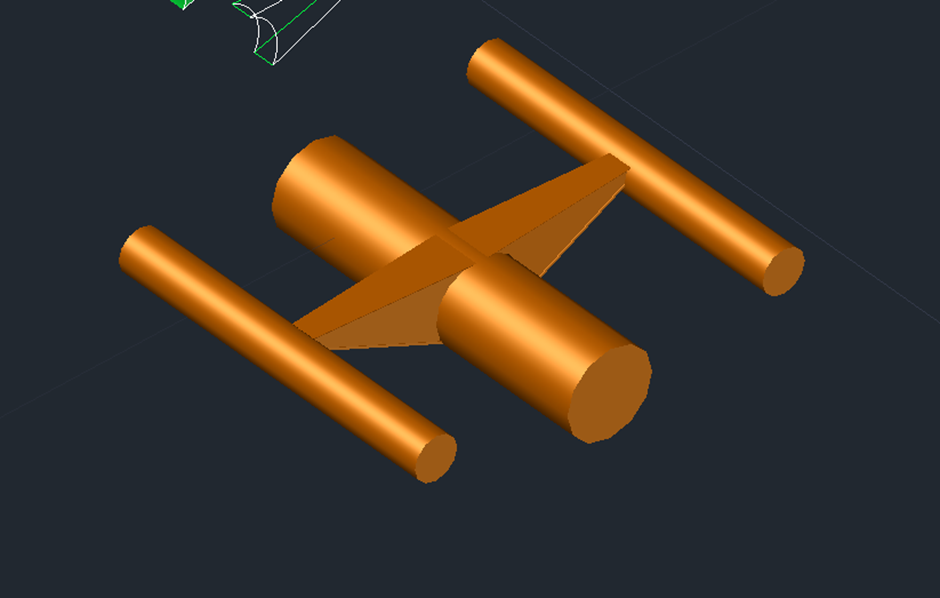
I then created three “beams” from a top-down view. These would be used to see what the track piece would look like from above. I measured where abouts the lines on the circles lined up before and created a new layer and drawing the needed pieces:

I then copied and pasted the pieces a distance of 1.6ft from each other as this is how much I measured the distance to be on the reference images.
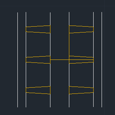
To finish visualising, I pasted multiple times and mirrored until I was happy with the result:
With this visualisation complete, I went back to the first track piece and mirrored it on itself and annotated any important pieces of information:

I could now create the “overhang” that the track has. This was done by measuring and offsetting the top and bottom lines and trimming any excess.
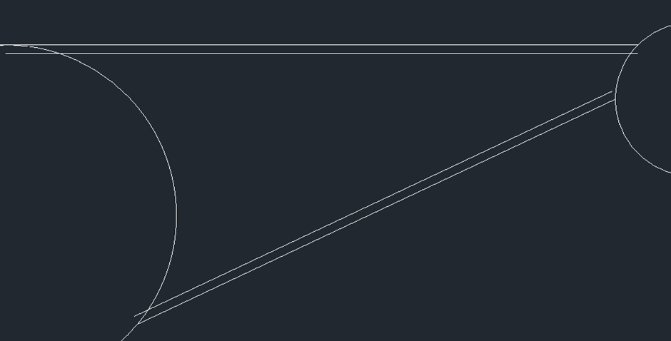
I then extruded the middle and side circles to represent the rails and make it easier to see how the track piece would fit in:
With the leftover lines, I used the patch tool to create the middle and overhang pieces of the track.
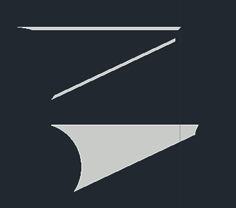
I flipped the main track piece on its side and created a new layer. By doing this and combining with the rotate and line tools, I made a hollow shell of the main rail piece:
This piece could now be extruded and placed back along the rails which are represented in blue:
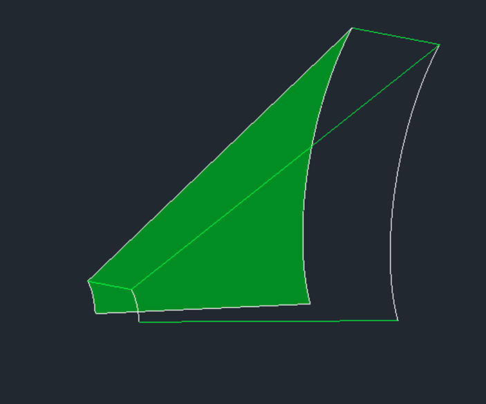
I now simply extruded the overhang pieces and pasted on top and below the previously created track piece:

Once I recoloured the piece, it left me with a basic visualisation of what the final track piece would look like:
After looking at this, I removed the middle and side rails and focused primarily on the centre. By drawing lines representing where the centre of the side rails would be and leaving space in the middle, I could copy the track piece along the model and use it to create the side rails accurately later on.

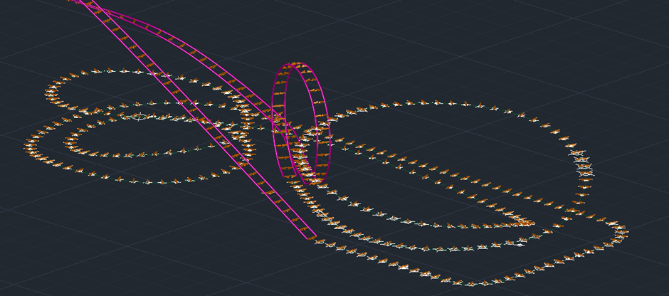
Once again using the reference photos to assist the making of the model, I calculated the space needed in between each rail piece. By using the divide tool, it placed points along the track that represented where each rail piece was required.
With these points in place, I pasted the individual track pieces on each point on the first piece of the model:
With this completed, I was left with the very long task of individually rotating each track piece so that it was facing the next piece. I did this using the 3D rotate tools and by modifying the UCS to allow rotations that were not otherwise possible.
Once this was done, the process become much easier as I created a spline going through each line created from the track piece and extruding a 0.4 radius circle along the path. I then did this for the other side leaving me with the completed rail for the first segment:

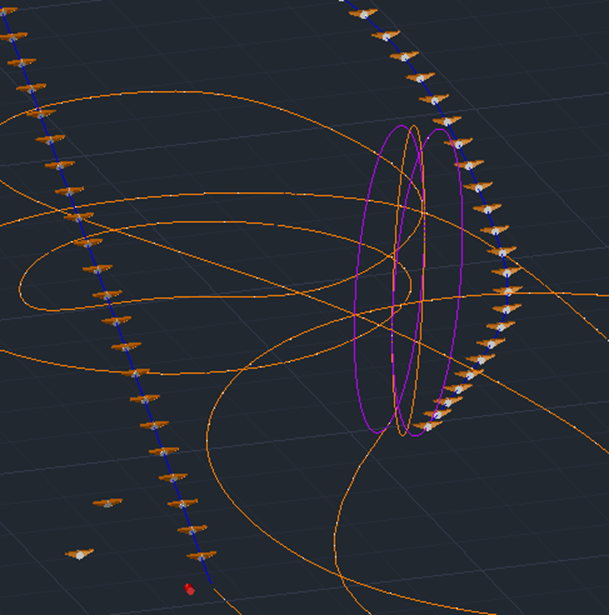
Next came the loop, this was not as difficult as first anticipated due to being able to paste the track pieces accordingly and 3d rotate to face the next piece:

I could now copy the extrusion method from the first segment and combine the spline and sweep tools to finish off the loop:
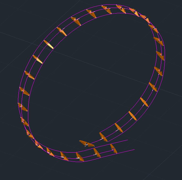

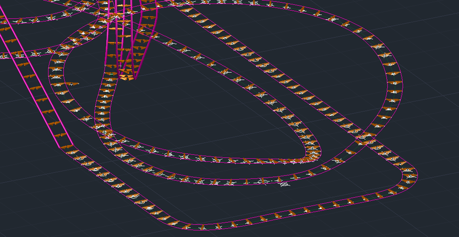
Now came the final and longest part of the model. This part required the most time out of the model and was by far the most tedious piece to model. I started off by using the divide tool to set out where the track pieces would go and pasting the pieces accordingly:
Once each piece was placed, the long task of rotating each piece started. This took at least two hours to do but left the track very near completion:
It was now a matter of simply splining the lines and using the sweep tool once again to finish off this segment:
Now all the track was completed, I recoloured the model to better represent the coaster itself:
The final part of the model was the structures. Luckily, the lines used at the start of the model lined up perfectly with the newly added railing.
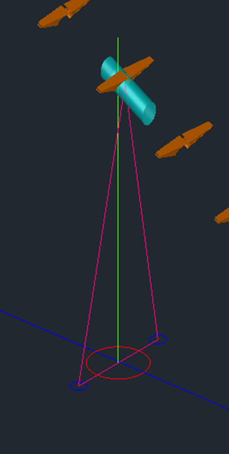
To create the structures, cylinders were created and then through use of the subtract tool, halved.
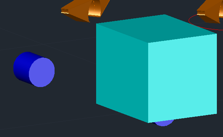
These pieces would represent the underside of the track that the support beams would be connected to. I created one of these pieces for each support and rotated accordingly with the model before changing layer to avoid later confusion:

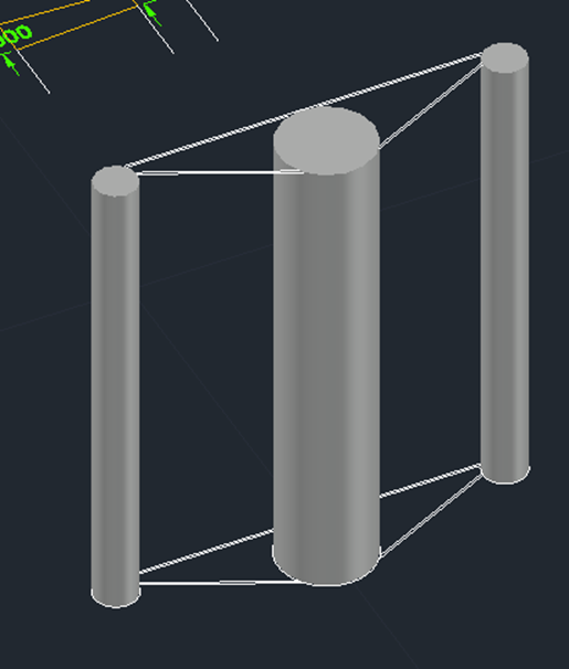
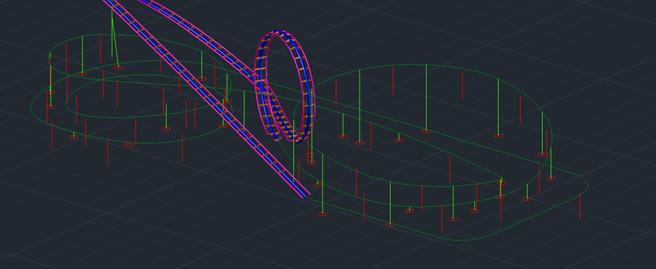
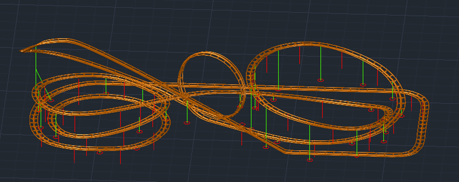
Now that all these pieces were in place, I created blue structure circles around the model to show where the poles would be inserted. I placed them accordingly to the real-life coaster and then used a separate layer to connect these circles to the centre point of the recently made underside pieces.
By extruding the blue circles along the pink layer, it created the perfect support beams for the model:
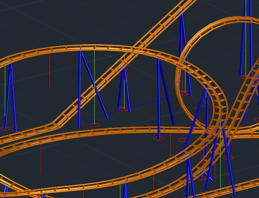
Finally, I placed boxes accordingly underneath each support for a bit of decoration and removed all unnecessary layers leading me to the final model:

With the model finally completed. I had some trouble converting it to an appropriate FBX format for rendering. To counteract this, I imported the model into 3DS Max and made a few adjustments to the track where the it did not convert properly.

By having the model in 3DS Max, it allowed me to export as an FBX file. With this file I could now paste the model into TwinMotion ready for rendering. I decided to use TwinMotion to render this model for a multitude of reasons. Firstly, TwinMotion allows real time rendering, allowing me to see immediate visual feedback as I made changes to the 3D scene. It is also extremely simple to use and allows easy integration through its use of FBX files.
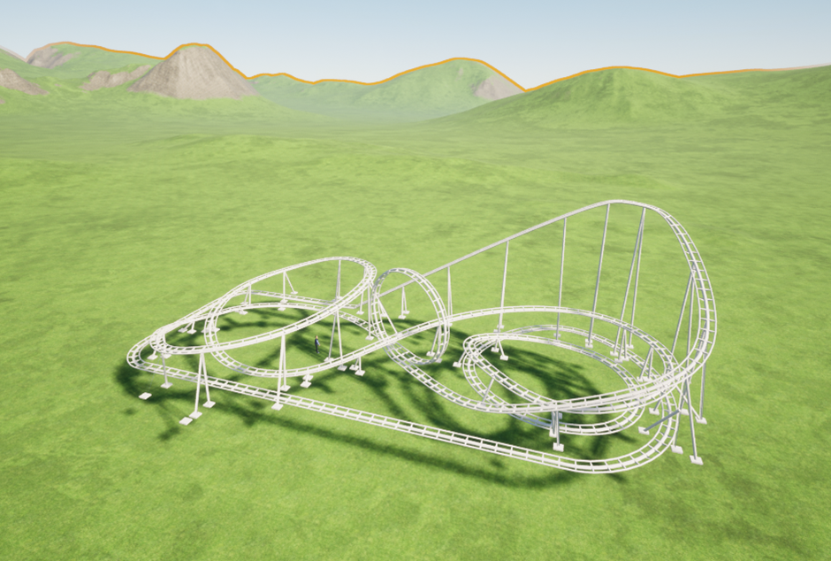
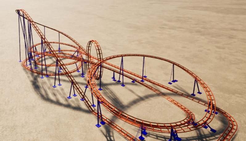
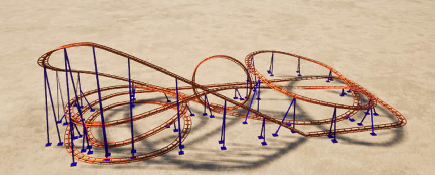
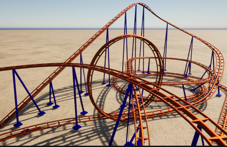
Luckily, the TwinMotion engine was very easy to use and by switching the grass out for sand and digging where the track went slightly under ground level, it left me with the appropriate terrain. It was now a matter of applying the steel material to the track and recolouring to leave me with the completed Scorpion model:

Conclusion
Due to this being my own personal project, the only outcomes required were the ones specified within the introduction, eliminating the need for any handover documents. I feel that I have completed these objectives successfully and have built a sustainable model with lots of potential.
I am also happy with the scale with it matching the height and length of the real coaster matching up perfectly, especially due to this being one of the key threats about modelling this roller coaster outlined in the SWOT analysis. This made the coaster have that much more realism and was one of the key aims I wanted to hit when making this model.
Another part of the model I am extremely happy with is how the supports integrate into the track. With this being the case, it makes it very possible to 3D print in the future with these supports being separate to the model and easy to make printable parts out of.
The final part I am happy with is the look of the loop and how it seamlessly attaches to the rest of the track whilst keeping its smooth transaction to the next piece. It looks perfectly in place and went a lot better than expected with this being one of the features I was most worried about putting into the model.
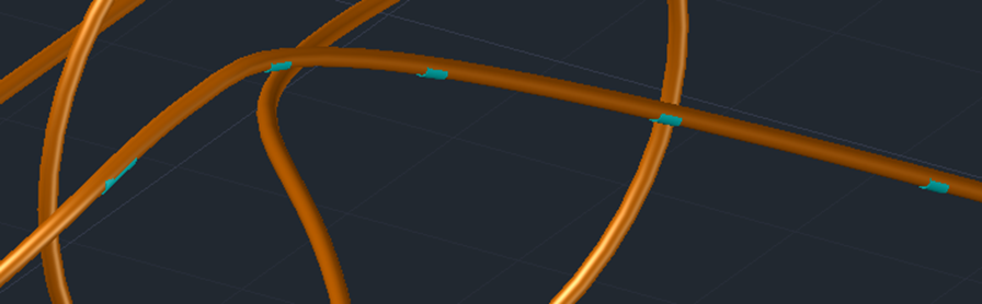
If I were to change anything about this project, I would like to create an environment around the coaster and add more details such as track pieces supporting the loop and the chain lift hill. I would also like to potentially 3D print the model and design the car so the model fully functions in real life. I also noticed a few missing assets on the track and given more time, would like to explore why this is the case and fix them. These assets interfered with the smoothness of the track and removed parts of the structures leading to a slightly glitchy looking final product.
There is a possibility I could continue this project next semester and if this is the case, these plans could very easily come into fruition. There is also the possibility of collaborating with Busch Gardens in hope of obtaining approval for future projects and potentially showcasing the model on their website or within their theme park and gaining certain design specifications for a more accurate product.
References
Conti, J. (2023). Santa Monica West Coaster image. The Hollywood Sign. Available at: https://www.hollywoodsign.org/blog/amuse-yourself-at-santa-monica-pier [Accessed 6 Dec. 2023].
RicksTrips (2015). Scorpion Busch Gardens. Youtube – Scorpion Busch Gardens. Available at: https://www.youtube.com/watch?v=EsSARK4i9KQ&ab_channel=RicksTrips [Accessed 16 Dec. 2023].
Scheer, S. (2009). Colossus – Thorpe Park. Wikipedia. Available at: https://upload.wikimedia.org/wikipedia/commons/thumb/9/96/Colossus-Thorpe-1.jpg/375px-Colossus-Thorpe-1.jpg [Accessed 11 Dec. 2023].